
Installation manual


Publication 1394-IN002B-EN-P — February 2004
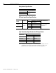
4-12 Troubleshooting Status Indicators
Presence of noise on
Command or resolver signal
wires
Recommended grounding per installation instructions and
Appendix B has not been followed.
• Verify grounding.
• Route wire away from noise sources.
External 50/60 Hz line frequency may be present.
• Verify grounding.
• Route wire away from noise sources.
External 100/120 Hz from a single phase logic supply may be
present.
• Verify grounding.
• Route wire away from noise sources.
External180 or 360 Hz from other adjustable speed drives may
be present.
• Verify grounding.
• Route wire away from noise sources.
Variable frequency may be velocity feedback ripple or a
disturbance caused by gear teeth or ballscrew balls etc. The
frequency may be a multiple of the motor power transmission
components or ballscrew speeds resulting in velocity
disturbance.
• Decouple the motor for verification.
• Check and improve mechanical
performance of the gearbox, ballscrew,
etc.
No Rotation
The motor connections are loose or open. Check motor wiring and connections.
Foreign matter is lodged in the motor. Remove foreign matter.
The motor load is excessive. Size the servo system.
The bearings are worn. Return the motor for repair.
The motor brake is engaged (if supplied).
• Check brake wiring and function.
• Return the motor for repair.
The motor is not connect to the load. Check coupling.
Overheating
The duty cycle is excessive.
Change the command profile to reduce accel/
decel or increase time.
The rotor is partially demagnetized causing excessive motor
current.
Return the motor for repair.
Abnormal Noise
Motor tuning parameters are set too high. Run auto tune again.
Loose parts are present in the motor.
• Return motor for repair.
• Replace motor.
Mounting bolts are loose. Tighten bolts.
Shaft key loose. Check coupling.
The bearings are worn. Return motor for repair.
Erratic Operation - Motor
locks into position, runs
without control or with
reduced torque
Phases U1 and V1, U1 and W1 or V1 and W1 reversed. Check and correct motor power wiring.
Sine, Cosine or Rotor leads are reversed in the feedback cable
connector.
Check and correct motor feedback wiring.
Sine, Cosine, Rotor lead sets of resolver feedback are reversed. Check and correct motor feedback wiring.
Condition: Potential Cause is: Possible Resolution is: