
Installation manual


Publication 1394-IN002B-EN-P — February 2004
B-4 Interconnect Diagrams
Shunt Module Interconnect
Diagrams
In the figure below, the 1394 system module is shown wired for
internal shunt operation. This is the factory default jumper setting.
Figure B.3
Internal Shunt Interconnect Diagram
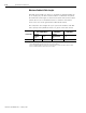
In the figure below, the 1394C-SJT05-D and -SJT10-D system modules
are shown wired with the optional external shunt resistor.
Figure B.4
External Shunt Module Interconnect Diagram (optional)
IMPORTANT
Internal shunt operation is only present on the 1394
system modules listed in Figure B.3.
DC+
INT
COL
1394 System Modules
1394C-SJT05-D or
1394C-SJT10-D
Shunt Power
Connector
DC+
INT
COL
DC+
COL
External Passive
Shunt Module
1394-SR10A
1394 System Modules
1394C-SJT05-D or
1394C-SJT10-D
Shunt Power
Connector