
Installation manual


Publication 1394-IN002B-EN-P — February 2004
Interconnect Diagrams B-5
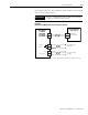
In the figure below, the 1394C-SJT22-D system module is show wired
with an external shunt resistor.
Figure B.5
External Shunt Module Interconnect Diagram (required)
1
The thermal switch and fan connections are only included with the 1394-SR36A and -SR36AF shunt modules.
IMPORTANT
All 1394 configurations with 22 kW system modules
require an external shunt module.
DC+
COL
DC+
COL
1394 System Module
1394C-SJT22-D
Shunt Power
Terminal Blocks
External Passive
Shunt Module
1394-SR9A,
1394-SR9AF,
1394-SR36A,
1394-SR36AF
Thermal
Switch
1
To customer-defined
control string
To customer-supplied
fan supply
Fan
Connections
1