
Installation manual


Publication 1394-IN002B-EN-P — February 2004
Interconnect Diagrams B-9
Thermal Switch and Brake
Interconnect Diagrams
This section provides thermal switch and brake interconnect diagrams.
Understanding Motor Thermal Switches
Thermal switches, internal to each servo motor, can be wired in series
to protect the motor from overheating. In the event of a fault
condition, the switch opens and the motor responds to the system
configuration. The explanation and example diagrams that follow
show how to wire motor thermal switches to your system module.
Depending on the series of your 1394 axis module, your customer
control devices may require isolation from the motor’s conducted
noise. When using 1394 (Series A and B) axis modules, an isolated
24V dc power supply and relay is recommended. 1394 (Series C) axis
modules contain internal motor brake and thermal switch filtering and
do not require the isolation power supply and relay.
Individual thermal fault monitoring can be achieved by wiring each of
the motor thermal switches from the motor, through TB1/TB2 on the
axis module, or directly from the motor to one of four dedicated
thermal fault inputs on the system module. Your 1394 system can then
be configured to monitor and disable one or all four of the axes. As an
alternative, you can wire the thermal switches into the start/stop string
to disable all axes when a fault occurs.
How Your Feedback Cable Affects Thermal Switch Wiring
The examples shown on the following pages are for 1326AB/AS servo
motors with resolver feedback (using 1326-CCU-xxx feedback cables).
The motor thermal switch leads are in the motor power cable and
attach to TB1 of the axis module (refer to figures B.7 and B.8 for
motor/axis module interconnect diagrams).
1326AB (M2L/S2L) motors and MP-Series motors (both resolver and
high resolution feedback) use 2090-CDNFDMP-Sxx feedback cables.
The motor thermal switch wires are in the motor feedback cable and
attach directly to the feedback connector on the bottom of the 1394
system module. Refer to figures B.6 and B.7 for motor/system module
interconnect diagrams).
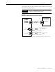
Thermal Switch Interconnect Diagrams
The example in Figure B.9 shows 1394 (Series C) axis modules with
internal brake and thermal switch filtering. Separate isolation power
supply and relay are not required. Using this start/stop string
configuration all axes are disabled when any one motor faults.