
Installation manual


Publication 1394-IN002B-EN-P — February 2004
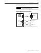
B-14 Interconnect Diagrams
Brake Interconnect Diagrams
The relay outputs (Output 0-3) are linked to the Brake Enable/Disable
configuration in RSLogix 5000 axis properties to allow control of a
motor brake for each axis. When an axis is enabled, the configured
output relay contact will close to disengage the associated motor
brake. At the same time, the axis will command sufficient torque to
hold the motor's position while the brake is disengaging. The length
of time that the axis will apply this torque is set by the Brake Off
Delay parameter for each axis. When an axis is disabled and the
motor has reached zero velocity, the configured output relay contact
will open to engage the associated motor brake. At the same time, the
axis will command sufficient torque to hold the motor's position while
the brake is engaging. The length of time that the axis will apply this
torque is set by the Brake On Delay parameter for each axis. Refer to
the 1394 SERCOS Interface Integration Manual (publication 1394-
IN024x-EN-P) to configure the brake parameters.
Depending on the series of your 1394 axis module, your brake
circuitry may require isolation from the motor's conducted noise.
When using 1394 Series B axis modules, an isolated 24V dc power
supply and relay is recommended. 1394 Series C axis modules contain
an internal motor brake filter and do not require the isolation power
supply and relay. The Series C brake filter also contains a bi-
directional snubber diode to protect the user-supplied 24V dc brake
power supply.
IMPORTANT
The output relay contacts are rated to control a 24V
dc motor brake rated up to 1A. Motor brakes rated
greater than 1A require an additional relay or
contactor with sufficient rating to handle the higher
current.