
Installation manual


8
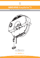
GDO-8V2 EasyRoller® II Owner Installation Instructions
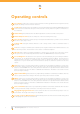
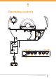
Operating controls
Prog input is used for the connection of the Automatic Technology PG-3 Universal Programmer for the
purpose of editing control and receiver functions.
P.E. Shunt The shunt has to be removed when connecting a Photo Electric (P.E.) Beam. NOTE: THE P.E. Shunt
must not be removed otherwise the opener will not function correctly. Remove only when a P.E. beam is to
be connected.
Status LED (yellow) indicates when the datum adjustment screw has reached correct position.
Datum Adjust Screw Used to set mid-point of door travel during limits set up.
Door Code button (blue) is used for storing or erasing the transmitter button you wish to use to command
the door to open, stop or close.
Coding LED (red) light indicates whether a code is being stored or when a transmitter button is
pressed.
Set button (orange) is used during the installation phase together with the Plus and Minus buttons to set
the door limit positions. The Set button is also used to re-initialise the Opener.
Operate button (blue) is used during installation to test the open, stop and close cycles for the opener.
The opener has to be initialised by the Set button before the OPERATE button becomes operable.
Force Margin Set The obstruction force pressure is set automatically by the opener during installation.
The pressure can be adjusted manually using the Force Margin Set button (White). Pressing the force
margin set button and open or close button will increase or decrease the amount of force. The Force
Margin Set is only ever used if other environmental factors (wind, etc.) affect the operations of the door/
opener.
Plus button (green - for limits setting and force margin) can be used during installation to set the open
limit position. Pressing this button will move the door in the open direction. Movement stops when the
button is released. NOTE: The open safety obstruction detection is inoperable whenever the Close Drive
button is used to move door. This button is disabled after initialisation. This button is also used to increase
the force margin sensitivity.
Open Limit LED (green) theled is very helpful during installation. It illuminates and fl ashes when the
door is opening and remains steady on when the open limit position has been reached.
Minus button (red - for limits setting and force margin) can be used during installation to set the close
limit position. Pressing this button will move the door in the close direction. Movement stops when the
button is released. NOTE: The close safety obstruction detection is inoperable whenever the Close Drive
button is used to move door. This button is disabled after initialisation. This button is also used to decrease
the force margin sensitivity.
Close Limit LED (red) the led is very helpful during installation. It illuminates and fl ashes when the door
is closing and remains steady on when the close limit position has been reached.
Engage/Disengagement Cord is used to switch the door into manual mode especially in case of a
power failure. The length of the string is also adjustable.
Security Lock for Manual Release (where fi tted) prevents the manual release handle being pulled
to disengage the opener into manual mode.
01
02
03
04
05
06
07
08
09
10
11
12
13
14
15