
Installation manual

26
GDO-9
Owner Installation Instructions
41
Fig
42
Fig
SmartSolar™ Installation
WARNING: Do not connect batteries until Step
21.3
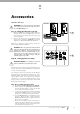
Step 21.1 - Mount the Charger Board
Unplug the drive unit from mains power.
Remove the screws, swing open the main cover. Then
remove the transformer, EMC board (if fi tted) and
mains power cable.
Mount the PCB support with two screws. Secure
the Solar charger board on to the PCB support with
3 screws. (Fig. 41).
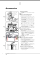
Plug the Charger Board’s three wire harness (red/
yellow/black) onto the control board’s “SBY-3”
connector (Fig. 42).
Plug the Charger Board’s white one wire harness
onto the control board’s “24vac in” connector (Fig.
42).
Plug the black solar shunt onto both pins of the
control board’s “JP1 Solar ” connector (Fig. 42)
IMPORTANT WARNING: Do not connect battery
or solar panel polarity incorrectly - this will result in
serious damage to components.
Step 21.2 - Connect the Solar Panel
Mount the solar panel as outlined in the SmartSolar™
Installation Manual.
Feed the Solar Panel’s cable through black grommet
located on the top of the plastic drive unit cover.
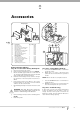
Connect the red wire to the Charger Board’s
“SOLAR+” connector, and the black wire to the
“–SOLAR” connector (Fig. 43).
WARNING: During Step 21.3 the opener will
become active.
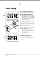
Step 21.3 - Mount & Connect the Battery
Mount the Battery Box close to the opener.
Feed the 2-core 18awg gauge cable (supplied)
through the Battery Box’s grommet.
Connect the red wire to the Battery Box’s “+” terminal,
and the black wire to the “–” terminal (Fig. 44).
Feed the other end of the battery cable through the
drive unit’s black grommet.
Connect the red wire to the Charger Board’s
“BAT+” connector, and the black wire to the “–
BAT” connector (Fig. 43).
Refi t the light diffuser and main cover.
Step 21.4 - Re-setup and Test the Opener
Setup travel limits and code transmitters as per the
GDO-9 instruction manual.
Press either the OPERATE button or use a transmitter
to operate the opener.
a.
b.
c.
d.
e.
f.
a.
b.
c.
a.
b.
c.
d.
e.
f.
a.
b.
B
l
a
c
k
(
F
r
o
m
B
a
t
t
e
r
y
)
R
e
d
(
F
r
o
m
B
a
t
t
e
r
y
)
R
e
d
W
h
i
t
e
Y
e
l
l
o
w
B
l
a
c
k
B
l
a
c
k
(
F
r
o
m
S
o
l
a
r
P
a
n
e
l
)
R
e
d
(
F
r
o
m
So
l
a
r
P
a
n
e
l
)
43
Fig
Re
d
W
i
r
e
B
lack Wire
44
Fig
Accessories
JP1 Solar
Shunt
Screws
PCB support
Screws taptite ‘S’ M4x8
Solar charger board
Screws taptite ‘P’ M4x8