
Instruction manual

T4x-SERIES QUICKSTART GUIDE
10
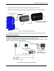
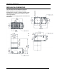
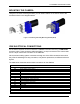
MOUNTING THE CAMERA
Using the T4x-Series mounting brackets, you can obtain rotation on the various axes of the
camera as shown in the diagrams below.
Figure 3 –Positioning with Body Mounting Bracket (Back)
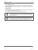
CBX ELECTRICAL CONNECTIONS
All T4x-Series cameras can be connected to a CBX500 connection box using a CAB-SCSxx
accessory cable. These accessory cables terminate in a 19-pin connector on the camera side
and in a 25-pin male D-sub connector on the CBX side.
We recommend making system connections through one of the CBX connection boxes since
they offer the advantages of easy connection, easy device replacement, and filtered reference
signals.
The table below shows the terminal block connections for the CBX500.
CBX500 Terminal Block Connectors
Input Power
Vdc
Power Supply Input Voltage +
GND
Power Supply Input Voltage -
Earth
Protection Earth Ground (See Caution)
Inputs
+V
Power Source – External Trigger
I1A
External Trigger A (polarity insensitive)
I1B
External Trigger B (polarity insensitive)
-V
Power Reference – External Trigger
+V
Power Source – Inputs
I2A
Input 2 A (polarity insensitive)
I2B
Input 2 B (polarity insensitive)
I3A
NOT USED
I4A
NOT USED
I34B
NOT USED
-V
Power Reference – Inputs
Shield
Shield
Network Cable Shield