
Instruction manual

POWER SUPPLY
11
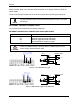
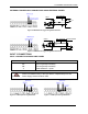
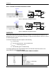
Outputs
+V
Power Source - Outputs
-V
Power Reference - Outputs
O1+
Output 1 +
O1-
Output 1 -
O2+
Output 2 +
O2-
Output 2 -
O3A
Strobe + / Output 3 + (See Note)
O3B
Strobe - / Output 3 -
RS232 Interface
TX
Transmit
RX
Receive
SGND
Signal Ground (See Caution)
Note: The strobe signal connection is shared with Output 3. If a non-zero value is defined for the Strobe Pulse Length
value (in VPM – Impact – General), the strobe is active. If the value is zero, Output 3 is active.
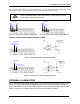
NOTE
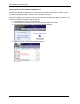
To avoid electromagnetic interference when the camera is connected to a
CBX connection box, verify the jumper positions in the CBX as indicated in
its Installation Manual.
POWER SUPPLY
NOTE
The T4x-Series does not support sourcing power towards the CBX through
the CBX "power from device" source jumper setting. Power must be
supplied to the CBX as shown below.
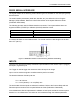
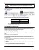
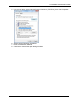
To power the camera and/or I/O devices through the CBX, power must be supplied to the
CBX500 spring clamp terminal pins as shown in Figure 4:
Figure 4 - Power Supply Connections
The power must be between 10 and 30 Vdc only.
It is recommended to connect the device CHASSIS to earth ground (Earth) by setting the
appropriate jumper in the CBX connection box. See the CBX Installation Manual for details.
CAUTION
Do not connect GND and SGND to different (external) ground references.
GND and SGND are internally connected through filtering circuitry which
can be permanently damaged if subjected to voltage drops over 0.8 Vdc.