
Instruction manual

T4x-SERIES QUICKSTART GUIDE
12
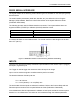
RS232 SERIAL INTERFACE
The signals relative to the following serial interface types are available on the CBX spring clamp
terminal blocks.
The serial interface parameters (baud rate, data bits, etc.) are defined in Vision Program
Manager (VPM) software. Refer to the Serial Port section of the Impact Reference Guide
(Publication # 843-0093).
The following pins are used for RS232 interface connection. The Impact software does not
support hardware (CTS/RTS) or software (Xon/Xoff) data flow control.
CBX500
Function
TX
Transmit Data
RX
Receive Data
SGND
Signal Ground
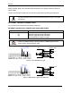
It is always advisable to use shielded cables. The overall maximum cable length must be less
than 15 m (49.2 ft.).
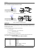
Figure 5 – RS232 Main Interface Connections Using Hardware Handshaking
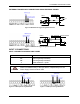
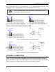
INPUTS
There are two optocoupled polarity insensitive inputs available on the camera: Input 1 (Trigger)
and Input 2, a generic input:
The Trigger is used to trigger the camera so that it will acquire an image.
Input 2 can be used as a signal to a software task to perform an action.
The electrical features of both inputs are:
V
AB
= 30 Vdc max.
I
IN
= 10 mA (camera) + 12 mA (CBX) max.
The active state of these inputs are selected in software. Refer to the Camera Setup tab and
Discrete Input tool sections of the Impact Reference Guide (Publication # 843-0093).
An anti-disturbance filter is implemented in software on both inputs so that the minimum pulse
duration is ≅ 0.5 milliseconds. This value can be increased through the software parameter