
Instruction manual

OUTPUTS
15
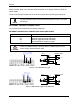
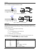
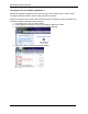
INPUT 2 CONNECTIONS USING EXTERNAL POWER
Camera
INPUT DEVICE
Vext 30 Vdc max.
D
E
V
CC
~
~
+
-
V
Signal
I2A
I2B
I
in
Figure 12 - PNP Input 2 Using External Power
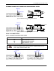
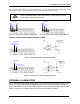
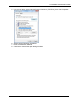
Camera
INPUT DEVICE
Vext 30 Vdc max.
D
E
Signal
V
V
CC
~
~
+
-
I2A
I2B
Figure 13 - NPN Input 2 Using External Power
OUTPUTS
Three optocoupled general purpose outputs are available. The meaning of the outputs can be
defined by the user. They are typically used either to signal the data collection result or to control
an external lighting system.
The electrical features of the two outputs are the following:
V
CE
= 30 Vdc max.
I
CE
= 40 mA continuous max.; 130 mA pulsed max.
V
CE saturation
= 1 Vdc max. @ 10 mA
P
D
= 80 mW Max. @ 45 °C ambient temp.
The output signals are fully programmable. Refer to the Discrete Output tool section in the
Impact Reference Guide for further details.
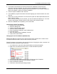
OUTPUT CONNECTIONS USING CBX POWER
CBX500
Function
+V
Power Source - Outputs
O1+
Output 1 +
O1-
Output 1 -
O2+
Output 2 +
O2-
Output 2 -
O3A
Strobe + / Output 3 + (See Note)
O3B
Strobe - / Output 3 -
-V
Power Reference Outputs