
Setup guide
5
Section
Panel Mounting Procedure
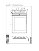
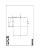
Cut and drill the panel (refer to Figure 2; Panel Mount Drawing Appendix G).
Measurements are in inches. A template of the hole pattern has been supplied
with your monitor to assist in making the mounting holes accurately. Also, there
is an AutoCad .dxf file included on the provided CD. This computer file can be
used in a design drawing or forwarded to your panel fabricator for the proper
mounting
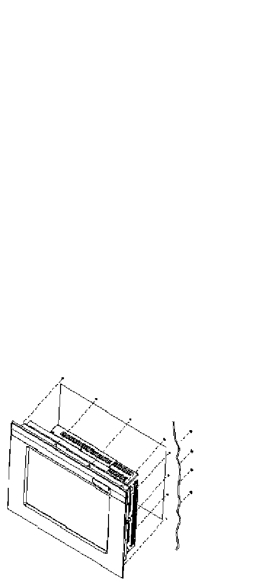
1. If access to the side of the monitor is not available following installation,
attach the power and video cables to the side of the monitor at this time.
2. Install the monitor in the prepared cutout.
3. Install the washers and lock nuts supplied with the monitor.
Note: Use #10-32 nuts for mounting.
4. Tighten all mounting nuts evenly to a torque of 24 inch-pounds.
ATTENTION: Mounting nuts must be tightened to a torque of 24 inch-pounds to
provide panel seal and avoid potential damage. AutomationDirect assumes no
responsibility for water or chemical damage to the monitor or other equipment
within the enclosure due to improper installation.
6. Attach the power, video and touch screen cables (if this is a –TS unit) to the
side of the monitor.
Figure 2: Panel Mount Drawing
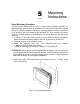
Mounting
Instructions