
Operating instructions


9
Copyright © 2013 Autonomic Controls, Inc. All Rights Reserved
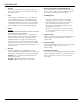
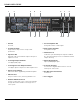
REAR PANEL GUIDE
1 2 3 4 5 6 7 8
9 10 11 12 13 14 15
1. AC Inlet
IEC socket
2. Speaker Terminals
Plug in terminal clamp connectors accept 1.5mm²
speaker wires.
3. Expansion Bus
RJ45 patch cable connects between expansion bus ports of
amplifiers in a stack.
4. Coax Digital Input Terminals
Coax digital (SPDIF) inputs.
5. Coax Digital Source Output Terminals
Coax digital outputs for expansion to further amplifier zones.
6. USB for programming
USB mini B socket for programming and firmware updates.
7. Ethernet Port
This port is used for control, monitoring and data access.
8. RS232 Communication Port
The port is used for setup, control or monitoring. A straight
through cable must be used when connecting to a PC or
control system.
9. Zone Preamplifier Out
Analog audio L/R Zone 7 and 8 outputs.
10. Analog Input Terminals
Analog audio L/R inputs
11. IR Emitter Ports
3.5mm mono jacks. IR9 & IR10 ports output the combined
IR1 – IR6 infra-red strings. Ports are not usable but are future
ready for IR routing.
12. Optical Digital Inputs
Optical (TOSLINK) digital inputs.
13. Controller Interface
For connection to keypads and IR receivers. 8 controller
interface ports - RJ45 sockets.
14. Bus Run Controller Interface
For future use.
15. Zone Triggers