
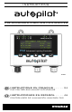
Installation Manual


Hydrofarm.com
8
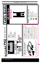
CABLE GUIDE
Advanced Digital & Analog
Lighting Controller
(APDPX2)
Fixtures are not shown to scale.
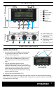
IMPORTANT: Do not attach data link cables to AC power cable. Always keep low voltage data cables and high voltage AC
power harness as far as possible from each other for stable signal transmission. Avoid coiling data cables as well as AC
harnesses in tight coils. Excess cable should be managed by creating long loops as opposed to tight coils.
LEGEND: LED Fixtures
ZONE A
Controls up to
50 LED fixtures.
ZONE B
Controls up to
50 LED fixtures.
PHOTOBIO
LED Fixtures
Note: Zone A and Zone B
can be set up in one room,
or in two separate rooms.
PTB
Link Cable
PTB Link Cable
PHOTO•LOC
Cable
CHC882000B
Female end
Male end
T Connector
• For use with PHOTOBIO X, M, T, and T Duo
• Includes 2 cables and 1 T Connector
1 Attach BLACK female end of the first
cable to the
ORANGE male end of the
PTB link cable (included with PX2).
2 Attach ORANGE male end of the
first cable to the
BLACK female
side of the T connector (trunk line).
3 Attach BLACK female end of the
second cable to the
ORANGE male
bottom of the T connector (branch line).
4 Attach ORANGE male end of the
second cable (branch line) to fixture.
5 Repeat steps 1–4 for each fixture.
PHOTO•LOC 0–10V Cable Kit
CHC882000B (sold separately)