
User guide

47
F.
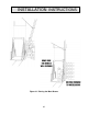
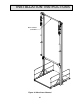
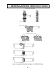
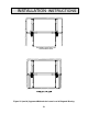
BRACING THE BEAMS (Reference Figure 25)
All illustrations on the GA drawing for bracing preferences are for reference only. Site
conditions may require different anchoring and bracing. The installers are ultimately
responsible for the proper and safe anchoring and bracing of the equipment.
Autoquip
Corporation supplies material for bracing on standard applications, but special bracing
may be required by the installer on non-standard models. The special materials for
anchoring and bracing of the lift and gates are not the responsibility of
Autoquip.
NOTE: For all field welding of braces, use 1/4" fillet – all around.
Items needed:
Qty Description
Varies Horizontal Brace Channel
varies Diagonal Channel Brace (when applicable)
varies Brace Plates – with (4) 9/16” dia. holes each
varies Side Channel Brace (when applicable)
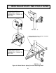
HORIZONTAL / UPPER LEVEL BRACING
1. Attach the horizontal channel brace to the upper floor landings with either lags or
by welding (it has been assumed that you will have a solid floor face to attach to
for your installation). When attaching the floor to beam brace, use bolts which
have been properly sized to withstand the horizontal pull-out force shown on the
GA drawing.
CAUTION!
Never use concrete anchor bolts on a cinderblock or brick wall! (Ref. Fig.
25) The wall will not withstand the pull force developed by the lift. Use only
recommended anchoring and bracing methods illustrated in this manual.
Equipment damage or personal injury could result.
2. Add side bracing as necessary for your particular installation in order to prevent
the beams from flexing or swaying sideways during operation.
3. Weld additional mast cross bracing to keep mast beams from spreading, quantity
depends on travel (refer to GA drawing). Take necessary precautions to
minimize beam movement resulting from the heating & cooling of welds. Re-
check and confirm guide angle dimension.
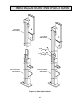
DIAGONAL BRACING (when used)
4. Install upper and lower diagonal bracing per the GA drawing for your installation
in order to prevent bowing of the beams during operation.
INSTALLATION INSTRUCTIONS