INSTALLATION, OPERATION AND SERVICE MANUAL MECHANICAL SCISSORS LIFT P.O. Box 1058 • 1058 West Industrial Avenue • Guthrie, OK 73044-1058 • 405-282-5200 • FAX: 405-282-8105 • www.autoquip.com Item # 830LA Version 1.
TABLE OF CONTENTS Identification and Inspection 3 Dangers and Warnings 4 Label Identification 8 Specifications 11 Lift Blocking Instructions 12 Installation Instructions 14 Operating Instructions 17 Routine Maintenance 18 General Maintenance 19 Replacement Parts List 21 Troubleshooting Analysis 22 IMPORTANT Please read and understand this manual prior to installation or operation of this lift. Failure to do so could lead to property damage and/or serious personal injury.
IDENTIFICATION & INSPECTION IDENTIFICATION When ordering parts or requesting information or service on this equipment, PLEASE REFER TO THE MODEL AND SERIAL NUMBER. This information is on a nameplate attached to the leg assembly. Replacement parts are available from a local Autoquip distributor. INSPECTION Immediately upon receipt of the unit, a visual inspection should be made to determine that it has not been damaged in transit. Any damage found must be noted on the delivery receipt.
DANGERS, WARNINGS & CAUTIONS SAFETY ALERTS (Required Reading!) The following SAFETY ALERTS are intended to create awareness of owners, operators, and maintenance personnel of the potential safety hazards and the steps that must be taken to avoid accidents. These same alerts are inserted throughout this manual to identify specific hazards that may endanger uninformed personnel. Identification of every conceivable hazardous situation is impossible.
DANGERS, WARNINGS & CAUTIONS Read and understand this manual and all labels prior to operating or servicing the scissors lift. All labels are provided in accordance with ANSI Z535.4. DANGER! Do not work under lift without Maintenance Device! To avoid personal injury, NEVER go under the lift platform until the load is removed and the scissors mechanism is securely blocked in the open position. See "Lift Blocking Instructions" section.
DANGERS, WARNINGS & CAUTIONS DANGER! Scissors lifts are designed individually for a specific load and application. To avoid personal injury, do not change the load or application from the original design. WARNING! NEVER stand, sit or ride on the lift! WARNING! All warning and information decals should be in place as outlined in the “Label Identification” section. If decals are missing or damaged, they should be replaced with new ones. Contact Autoquip for replacements.
DANGERS, WARNINGS & CAUTIONS CAUTION! When moving the lift, do not attempt to pick it up by the platform; it is hinged and could be damaged. Pick up from under the base frame ONLY. CAUTION! Do not continue to activate the “UP” button if the lift is not raising or if it has reached the fully raised position. To do so may result in permanent damage to the lift.
LABEL IDENTIFICATION 2 3 1 4 5 Figure 1 Label Placement Diagram Mechanical Lift Item No. Qty Description 1 2 Danger – Do Not Put Hands or Feet . . . 36430050 2 2 Max. Capacity 36405710 3 2 Caution – Familiarize Yourself with Operators Manual 36401487 4 2 Danger – Do Not Disassemble Motor / Gearbox 36405110 5 1 Autoquip Serial Number Nameplate 36401511 8 Part No.
LABEL IDENTIFICATION Note: Labels shown here are not actual size.
LABEL IDENTIFICATION Figure 5 Label 36405110 Figure 6 Label 36401511 10
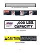
SPECIFICATIONS LOAD CAPACITY The load capacity rating is stamped on a metal plate attached to one side of the lift. This figure is a net capacity rating for a lift furnished with the standard platform. Where gravity roll-sections, special tops, etc, are installed on the lift after leaving the plant, deduct the weight of these from the load rating to obtain the net capacity. Lifts should not be overloaded beyond the established capacity as damage and/or personal injury may result.
LIFT BLOCKING INSTRUCTIONS 1. Remove all load from the platform. Never block the lift when loaded. 2. Raise the platform sufficiently for the base rollers to rollback past the flip-over maintenance locks, located on the base frame of the lift. 3. Engage both maintenance locks by flipping them over (see Figure 7). 4. Lower the platform until the base rollers just come into contact with and rest against the maintenance locks. 5.
LIFT BLOCKING INSTRUCTIONS FLIP-OVER MAINTENANCE LOCKS SHOWN IN PLACE ON BOTH SIDES OF BASE FRAME Figure 7 Lift Blocking Diagram 13
INSTALLATION INSTRUCTIONS FLOOR INSTALLATION 1. Make sure installation area is clean before starting. 2. If the permanent electrical work is not complete, some means of temporary lines with an on-off device for the power supply should be set up for testing purposes. 3. Place the lift in the installation area. CAUTION! When moving the lift do not attempt to pick it up by the platform; it is hinged and could be damaged. Pick up from under the base frame ONLY. 4. Make temporary electrical connections.
INSTALLATION INSTRUCTIONS PIT INSTALLATION -- MODELS WITH BEVEL TOE GUARDS DANGER! Do not install the lift in a pit unless it has a bevel toe guard or other approved toe protection. A shear point can exist which can cause severe injury to the foot. 1. Check the pit dimensions. Length and width should be 2" minimum longer and wider than the lift platform. Depth should include ½” allowance for shims or grout. 2. Check the chase entrance into the pit. The diameter should be 3".
INSTALLATION INSTRUCTIONS DANGER! Do not work under lift without Maintenance Device! To avoid personal injury, NEVER go under the lift platform until the load is removed and the scissors mechanism is securely blocked in the open position. See "Lift Blocking Instructions" section. 6. The base frame of the lift has pre-drilled holes for lagging the lift securely to the floor. Mark holes, drill, and install with anchors. Lifts with oversize platforms have minimum pull out requirements of 2,000 lbs.
OPERATING INSTRUCTIONS 1. Mechanical actuators have a maximum lifting capacity (see “Specifications” section). Lifting loads exceeding the rated capacity of the lift may result in excessive wear and damage to the actuator or equipment structure. WARNING! NEVER stand, sit or ride on the lift! 2. This lift is designed for in-plant applications and is furnished with constant pressure pushbutton controls. Actuating the "UP" button will energize the lift actuator and cause the lift to rise. 3.
ROUTINE MAINTENANCE Normally, mechanical lifts and tilters require very little maintenance. However, a routine maintenance program could prevent costly replacement of parts and/or downtime. WARNING! To avoid personal injury, NEVER go under the lift platform or perform any maintenance on the equipment until the load is removed and the platform or scissors mechanism is securely blocked in the open position. See the "Lift Blocking Instructions" section. MONTHLY INSPECTION 1.
GENERAL MAINTENANCE ACTUATOR REMOVAL AND REPLACEMENT WARNING! To avoid personal injury, NEVER go under the lift platform or perform any maintenance on the equipment until the load is removed and the platform or scissors mechanism is securely blocked in the open position. See the "Lift Blocking Instructions" section. 1. Securely block open the lift - see the "Lift Blocking Instructions”. 2. Always shut off the main electrical switch, when blocked, to prevent someone from turning it on. 3.
L1 L2 L3 460 VOLT 60 CYCLE 3 PHASE 20 Figure 8 Electrical Schematic 3 3 3 6 3 P.B. 4 3 3 1-6/10 AMP. FUSE 6/10 AMP. FUSE (BY OTHERS) FUSED DISCONNECT (BY OTHERS) MS 2 MS 1 2 XFMR. REV. FWD. L2 TYPICAL PILOT CONTROLS ONLY CONTACTS REVERSE MS 2 CONTACTS CONTACT O.L. RELAY ELECTRICAL SCHEMATIC 5 115V. 460V. "DOWN" L.SW. 7 "UP" L.SW. 1 L1 L3 L2 L1 FORWARD MS 1 2 2 HEATERS O.L.
REPLACEMENT PARTS LIST Specific part numbers vary from job to job, depending on the model and options chosen for the application. Call the Autoquip Service Department with the serial number of the specific equipment to order the appropriate parts.
TROUBLESHOOTING ANALYSIS WARNING! To avoid personal injury, NEVER go under the lift platform or perform any maintenance on the equipment until the load is removed and the scissors mechanism is securely blocked in the open position. See the "Lift Blocking Instructions" section. PROBLEM Lift does not raise Lift drifts down slowly during non-operation. POSSIBLE CAUSE AND SOLUTION • The load may exceed the rating for the actuator.
TROUBLESHOOTING ANALYSIS PROBLEM Lift raises very slowly. Lift does not lower, or lowers very slowly. POSSIBLE CAUSE AND SOLUTION • The load may exceed the rating for the actuator. Refer to the “Specifications” section to ensure loads are within rated limits. • There may not be enough amps available. Check the supply amperage to ensure it provides the minimum amperage needed per the vendor’s specifications (contact information is in the “General Maintenance” section).