INSTALLATION, OPERATION AND SERVICE MANUAL LOW REACH PAN LIFT Model XLR P.O. Box 1058 • 1058 West Industrial Avenue • Guthrie, OK 73044-1058 • 405-282-5200 • FAX: 405-282-8105 • www.autoquip.com 830XLR Version 1.
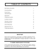
TABLE OF CONTENTS Identification and Inspection 3 Safety Signal Words 4 Safety Practices 5 Label Identification 8 Specifications 11 Lift Blocking Instructions 13 Installation Instructions 16 Operating Instructions 18 Routine Maintenance 19 General Maintenance 21 Replacement Parts List 32 Troubleshooting Analysis 33 IMPORTANT Please read and understand this manual prior to installation or operation of this lift.
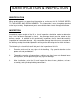
IDENTIFICATION & INSPECTION IDENTIFICATION When ordering parts or requesting information or service on this lift, PLEASE REFER TO THE MODEL AND SERIAL NUMBER. This information is on a nameplate attached to the leg assembly. Replacement parts are available from a local Autoquip distributor. INSPECTION Immediately upon receipt of the lift, a visual inspection should be made to determine that it has not been damaged in transit. Any damage found must be noted on the delivery receipt.
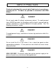
SAFETY SIGNAL WORDS SAFETY ALERTS (Required Reading!) The following SAFETY ALERTS are intended to create awareness of owners, operators, and maintenance personnel of the potential safety hazards and the steps that must be taken to avoid accidents. These same alerts are inserted throughout this manual to identify specific hazards that may endanger uninformed personnel. Identification of every conceivable hazardous situation is impossible.
SAFETY PRACTICES Read and understand this manual and all labels prior to operating or servicing the lift. All labels are provided in accordance with ANSI Z535.4. DANGER ! Do not work under lift without maintenance device! To avoid personal injury, NEVER go under the lift platform until the load is removed and the scissors mechanism is securely blocked in the open position. See "Lift Blocking Instructions" section.
SAFETY PRACTICES DANGER! Extending the platform length or width beyond the factory limit could cause the unit to tip, which could result in personal injury or death. DANGER! Do not attempt to remove the velocity fuse until the maintenance locks securely support the lift and all hydraulic pressure has been removed from the lifting cylinders and hydraulic hoses.
SAFETY PRACTICES CAUTION! Never run the pump for more than a couple of seconds without pumping oil. This applies to low oil conditions, improper motor rotation, running the pump against the relief pressure after the lift is fully raised against the physical stops, running overloaded beyond capacity, or running at reduced speed because of pinched or obstructed hydraulic lines.
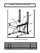
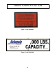
LABEL IDENTIFICATION 2 5 1 3 4 Figure 1 Label Placement Diagram XLR Item No. 1 2 3 4 5 Qty 2 4 1 1 2 Description Caution – Familiarize Yourself With Operators Manual Danger – Do Not Put Hands or Feet . . . Autoquip Serial Number Nameplate Fill with Recommended Oils Only Capacity 8 Part No.
LABEL IDENTIFICATION Note: Labels shown here are not actual size.
LABEL IDENTIFICATION Figure 5 Label 36400661 Figure 6 Label 36401594 10
SPECIFICATIONS (in.) 36 36 36 36 36 36 36 36 36 Lifting Capacity (lbs.) 2000 2000 2000 3000 3000 3000 4000 4000 4000 Lowered Ht. (in.) 1/2 1/2 1/2 1/2 1/2 1/2 1/2 1/2 1/2 Side Reach -Over (in.
SPECIFICATIONS PUMP PRESSURE This lift incorporates a positive displacement pump machined to a high degree of accuracy and specially adapted to requirements of higher-pressure ranges over that of a standard pump. Therefore, standard factory models of the same manufacture cannot replace it. The pump can operate efficiently at intermittent pressures up to 3200 PSI and continuous duty to 2500 PSI.
LIFT BLOCKING INSTRUCTIONS WARNING ! Only authorized personnel should perform inspection or maintenance and service procedures. Unauthorized personnel attempting these procedures do so at the risk of personal injury or death. DANGER ! Failure to properly adhere to lift blocking procedures is to risk the sudden and uncontrolled descent of the lift during maintenance or inspection. A falling lift can cause severe injury or death.
LIFT BLOCKING INSTRUCTIONS FLIP-OVER MAINTENANCE LOCKS SHOWN IN PLACE ON BOTH SIDES OF BASE FRAME.
LIFT BLOCKING INSTRUCTIONS DANGER ! If for any reason you are unable to lower the lift completely onto the maintenance device(s), stop immediately and consult the factory. Failure to properly use the factory approved maintenance device(s) could result in severe injury or death. 5.
INSTALLATION INSTRUCTIONS 1. Make sure installation area is clean before starting. 2. If the permanent electrical work is not complete, some means of temporary lines with an on-off device for the power supply should be set up for testing purposes. 3. Place the lift in the installation area. CAUTION! When moving the lift, do not attempt to pick it up by the platform; it is hinged and could be damaged. Pick up the lift from under the base frame ONLY using a strap sling. 4.
INSTALLATION INSTRUCTIONS CLEAN UP 1. Clean up any debris from the area. A clean installation makes a good impression and creates a much safer environment! 2. Touch-up paint is available from Autoquip for repair of damaged paint surfaces. WARNING! All DANGER, WARNING, and CAUTION labels and informational decals and plates must be intact and in place on the lift. Contact an Autoquip representative if labels are missing or damaged. See “DANGERS, WARNINGS, and CAUTIONS” section of this manual.
OPERATING INSTRUCTIONS 1. Scissors lifts have maximum lifting capacity ratings (See the “Specifications” section). The safety relief valve has been factory set to open at a point slightly above the rated load and allows the oil to bypass into the reservoir. The safety relief valve should not be adjusted for any reason as it could cause the motor or pump to prematurely burn out. Applying loads exceeding the rated capacity of the lift may result in excessive wear and damage to the lift. 2.
ROUTINE MAINTENANCE Normally scissors lifts will require very little maintenance. However, a routine maintenance program could prevent costly replacement of parts and/or downtime. WARNING! To avoid personal injury, NEVER go under the lift platform or perform any maintenance on the lift until the load is removed and the scissors mechanism is securely blocked in the open position. See "Lift Blocking Instructions" section. MONTHLY INSPECTION 1.
ROUTINE MAINTENANCE Oil Viscosity Recommendations Environment Recommended Oil (Ambient Temperatures) Indoor location, variable 10W30 or 10W40 temperatures (30 - 100° F) Multiviscosity motor oil Indoor location, consistent SAE-20W motor oil Temperatures (70° F) Outdoor location, (-10 - 100° F) SAE 5W30 Multiviscosity motor oil Cold-storage warehouse 5W30 Multiviscosity (10 - 40° F) motor oil Freezer (-40° F to 0° F) Consult Factory OIL CAPACITY Standard polyethylene tank capacity is approximately five quart
GENERAL MAINTENANCE CYLINDER REPLACEMENT 1. Set the lift in the maintenance position (See LIFT BLOCKING INSTRUCTIONS on page 13.) 2. Unbolt the two hex head bolts that retain each of the cylinders to the platform. 3. Press and hold the “Down” button to allow the cylinders to retract to a position where they can be removed from the platform connection. 4. Disconnect electrical power. Always shut off the main electrical switch when maintenance is to be performed and flollow OSHA lockout-tagout procedures. 5.
Figure 8 Ram Detail 22 AIR BLEEDER SCREW W/ WASHER ROD END STOP DETAIL A ROD BUSHING RAM CASING SEAL/PACKING GLAND BACKUP RING QUAD RING RAM PLUNGER (SHOWN IN RETRACTED POSITION FOR SEAL REPLACEMENT) RAM CASING RAM PLUNGER (1-1/2" DIA.
GENERAL MAINTENANCE VELOCITY FUSE REPLACEMENT DANGER ! Do not attempt to remove the velocity fuse until the lift is securely supported with the maintenance locking devices and all hydraulic pressure has been removed from the lifting cylinders and hydraulic hoses. Failure to follow these instructions could result in personal injury or death! Never attempt to take a velocity fuse apart and repair it. These are precision devices that are factory assembled under exacting conditions.
GENERAL MAINTENANCE Figure 9 Hydraulic Schematic 24
GENERAL MAINTENANCE WIRING AUTOQUIP "SUPER TORQUE' MOTORS Because Autoquip "Super-Torque" motors actually deliver substantially more horsepower than their nameplate rating, they must always be wired for heavier currentdraw than standard motors of the same nameplate rating. However, because of the "Super-Torque" motor’s starting efficiency and superior running characteristics, circuit components do not have to be as large as for standard motors of equal delivered horsepower.
Figure 10 Electric Schematic; 115V/1Ph 26 (RED) OPTIONAL FOOTSWITCH W/ GUARD (NEMA 1) SHIPPED LOOSE WHEN ORDERED. TO BE INSTALLED AND WIRED (BY OTHERS) 3. TYPICAL PILOT CONTROLS ONLY ELECTRICAL SCHEMATIC TRANSFORMER PRIMARY CONNECTION DIAGRAMS ARE LOCATED ON INSIDE OF FRONT COVER. (GRN) L1 (WHEN USED) (BLACK) (GRN.) (WHITE) (BLACK) "UP" LIMIT SWITCH (XF) 2. PUSHBUTTON (WHITE) 2.
Figure 11 Electric Schematic; 230V/1Ph 27 OPTIONAL FOOTSWITCH W/ GUARD (NEMA 1) SHIPPED LOOSE WHEN ORDERED. TO BE INSTALLED AND WIRED (BY OTHERS) 3. TYPICAL PILOT CONTROLS ONLY ELECTRICAL SCHEMATIC L1 (WHEN USED) TRANSFORMER PRIMARY CONNECTION DIAGRAMS ARE LOCATED ON INSIDE OF FRONT COVER. (GRN) (GRN.) (WHITE) (BLACK) "UP" LIMIT SWITCH (XF) 2. PUSHBUTTON 2.
(WHT) 28 (WHT) (GRN) (GRN) Figure 12 Electric Schematic; 208-230-460V/3Ph FOOTSWITCH IS SHIPPED LOOSE FOR INSTALLATION BY OTHERS (WHEN ORDERED). 3. TYPICAL PILOT CONTROLS ONLY ELECTRICAL SCHEMATIC TRANSFORMER PRIMARY CONNECTION DIAGRAMS ARE LOCATED ON INSIDE OF FRONT COVER. 2. (WHEN USED) MOTOR STARTER, CONTROL TRANSFORMER, HEATERS, AND FUSES TO BE MOUNTED IN NEMA 1 ENCLOSURE, AND PRE-WIRED TO POWER UNIT. (RED) 6 6 (RED) L1 5 4 115VAC-(RED) 3 (A2) DN. SOL.
GENERAL MAINTENANCE Figure 13 Guarded Footswitch Assembly 29
GENERAL MAINTENANCE Figure 14 Pushbutton Assembly 30
GENERAL MAINTENANCE Figure 15 Limit Switch Wiring Diagram 31
REPLACEMENT PARTS LIST PART # 20001137 20022877 20023925 24002008 24012502 30000020 30300016 32701290 33000680 34000018 34000257 35103380 35105130 35107910 35107980 35107990 35108050 36202141 41050139 41501776 41800640 45400082 20013900 45503150 47900006 52500485 52502903 52600269 DESCRIPTION Tongue & Groove Coupling 18DU16 Bushing 24DU16 Bushing Washer, 1-1/8” x 1/64” Thick Washer, 1-1/2” x 1/16” Thick Motor, ¾ HP/1 PH Motor, 1 ½ HP/3 PH Down Solenoid Coil, 24 VAC Transformer Limit Switch Limit Switch Arm
TROUBLESHOOTING ANALYSIS DANGER ! To avoid personal injury, NEVER go under the lift platform until the load is removed and the scissors mechanism is securely blocked in the open position. See "Lift Blocking Instructions" section. PROBLEM Lift raises, then lowers back slowly. Lift lowers very slowly. POSSIBLE CAUSE AND SOLUTION • The "Down" solenoid may not be seating. Remove the solenoid coil and check again.
TROUBLESHOOTING ANALYSIS PROBLEM Lift does not raise. POSSIBLE CAUSE AND SOLUTION • The motor rotation for a 3-phase motor may be reversed. Reverse only two motor electrical leads. • Check for a line or hose leak. • Check for oil shortage in the reservoir. Add oil as necessary (See Oil Requirements in the “Routine Maintenance” section.) • The load may exceed the rating. (See the “Specifications” section.) Remove the excess load. • The suction filter may be clogged, starving the pump.
TROUBLESHOOTING ANALYSIS PROBLEM Lift won’t lower. POSSIBLE CAUSE AND SOLUTION • The solenoid coil may be incorrectly wired, burned out, not rated for the voltage, or the line voltage may be excessively low. Check voltage near the coil. • The velocity fuse may be locked. Do not attempt to remove the velocity fuse. The following steps should be followed: 1. Remove the load from the lift. Inspect all fittings, hoses, and other hydraulic components for leads or damage. 2.
TROUBLESHOOTING ANALYSIS PROBLEM Lift seems bouncy during operation. Motor labors or heats excessively. POSSIBLE CAUSE AND SOLUTION • Lower the lift to collapsed position and continue to hold “DOWN” button an additional 10-30 seconds to bleed air from the cylinder. Do not confuse spongy or jerky operation with small surges that may occur when operating on rough or uneven floors • Check for oil starvation. • The voltage may be low.