
Operating instructions
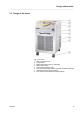
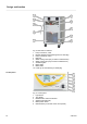
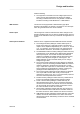
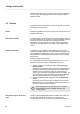

Fig. 2: Rear side VC 5000 W
1 Pump connection, outlet
2 Bypass adjusting wheel (starting with VC 1200 (W))
3 Pump connection, return
4 Drain tap
5 Water cooling outlet (only for water-cooled devices)
6 Water cooling inlet (only for water-cooled devices)
7 Ventilation grille
8 Rating plate
9 Mains cable
10 Fuses (up to and including VC 3000 (W))
Fig. 3: Control panel
1 Light sensor
2 TFT display
3 ENTER button and arrow buttons
4 Softkeys (left and right)
5 Mains power switch
6 USB interface (on the side of the control panel)
Control panel
Design and function
Variocool 16