
Installation guide


1
V0.04 FcN - July 5, 2011
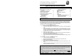
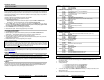
WIRING SCHEMATIC
For Automatic transmissions:
Cut the yellow loop before plugging
the module.
TACH Threshold: HIGH
TACH Threshold: NORMAL
Programming Button
SIDE VIEW OF THE MODULE
30 A Fuse
30 A Fuse
GREEN .................5
TH
RELAY
PURPLE .................STARTER
ORANGE ......ACCESSORIES
(Heater Blower Motor)
YELLOW .................IGNITION
RED ................+12V (Battery)
RED ................+12V (Battery)
15 A Fuse
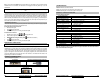
1- BLACK..........................GROUND (
-
)
2- PURPLE...........................TACH (AC)
3- GREY...................HOOD SWITCH (
-
)
4- ORANGE........... BRAKE SWITCH (+)
5- YELLOW .......PARKING LIGHTS (+/-)
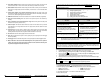
WARNING!
DO NOT SET
THE BLUE JUMPER TO
A HORIZONTAL POSITION
12- YELLOW .................. (+) Glow plug input
11- GREY ....................... (
-
) NEG. Door input
10- WHITE ..................... (
-
) GROUND when running
9- PURPLE .................... (
-
) EXT. TRIGGER output
8- ORANGE ................... (
-
) Parking Brakes input
7- WHITE/ORANGE .......(
-
) Starter kill output
6- BLUE/WHITE .............(+) POS. Door input
5- WHITE/GREEN ..........(
-
) DISARM output / PTS output
4- WHITE/BROWN .........(
-
) REARM output
3- GREEN ...................... (
-
) UNLOCK output
2- BROWN ..................... (
-
) LOCK output
1- BLUE ......................... (
-
) TRUNK output
1. GREY/LIGHT BLUE.... (-) AUX2 output
2. BLUE/WHITE............... (-) AUX1 output
3. YELLOW/WHITE......... (-) Negative Ignition output
N/A
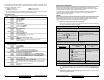
ADS & Fortin
bypass
Yellow loop
Jumper for Accessories 2
Jumper for Ignition 2
Jumper for Starter 2
INV 200
(Door lock pulse
inverter)
Parking lights jumper in
Neutral position
Positive Parking lights
Negative Parking lights
Optional programming
port / SmartStart
REAR VIEW OF THE MODULE
Xpresskit bypass