MANUAL TRANSMISSION REMOTE STARTER AS-2360 TW Installation Guide Notice The manufacturer will accept no responsibility for any electrical damage resulting from improper installation of the product, be that either damage to the vehicle itself or to the unit. This unit must be installed by a certified technician using all safety devices supplied. Please note that this guide has been written for properly trained Autostart technicians: a certain level of skills and knowledge is therefore assumed.
Table of Contents Table of Contents .....................................2 Introduction...............................................3 Included in the Kit .....................................3 Installation Points to Remember...............4 Harness Description .................................5 Flashing the Hood-Pin Switch.................12 The Programming Assistance Button .....13 Programming a Transmitter....................14 Before you Proceed................................
Introduction This guide contains all the information relevant and necessary for the installation of the module. Most of the features of this product are explained in the user guide. Therefore, if you need detailed information about a feature of the product, we recommend that you refer to the user guide. Included in the Kit Please carefully read the installation guide before beginning the installation, especially the harness description section and the programming options.
Installation Points to Remember ♦ Make sure that vehicles equipped with an automatic transmission do not start while in any of the drive gears. If the vehicle starts in gear, install a manual-transmission remote starter instead. ♦ When installing a manual-transmission product on a vehicle with a manual transmission, always make sure that all doors will get the unit out of ready mode. switch the wire used so that it is triggered by all doors.
Note: The parking light output relay of the unit gives two clicking sounds for each flash of the lights: one click when the lights would go ON and one click when the lights would go OFF.) ♦ Parking light flashes to which the text refers throughout this manual refer to the parking light output of the unit, not of the vehicle. Harness Description When connecting a module, it is important to make sure that the connector with the ground wire is connected first, before making the 12-volt connections.
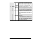
E F This wire will power the heater blower motor. Usually connected to the accessories wire of the vehicle. The source wire must have power with the ignition key in the IGNITION ON (RUN) position only (no power in the CRANK position). (+) Accessori Warning: at the ignition switch of certain vehicles, ORANGE es output (30 there may be more than one ignition wire for powering A) the heater blower motor. Use the 5th relay (Pin F) and extra relays to power up any extra ignition wires if necessary.
This wire provides a +12 V output and must be connected on the vehicle to the parking lights wire that tests +12 V when the light switch is in the ON (+) 12 V position. YELLOW Parking Light Note: ensure that the voltage does not decrease or output increase when the dimmer control switch is turned. If the voltage goes up or down, find another parking light wire.
7 8 P. 8 Caution! The installer should use either the positive or the negative Door input. Never use both of them simultaneously. It is essential that the Remote Car Starter be connected in such a way as will allow each one of the Doors to turn off Ready Mode: the driver-side Door Pin does not constitute by itself a sufficient connection. This wire will provide a constant 500 mA output when the system is armed (locked by remote control). It can be connected to an external starter interrupt relay.
The external trigger wire can be used for remotestarting the vehicle with an external device. When the vehicle is running, triggering this input will activate idle mode. The external trigger wire can also be used to operate as a negative trigger with the trunk pin-switch, the key sense wire or the door pinswitch: Option 1 Connects to negative trunk pin. When this wire is programmed for trunk pin, pressing TRUNK will activate a 1-second disarm output.
WHITE 11 GREY P. 10 This wire provides a constant 500 mA ground output while the module is running. This output becomes active at the same time as the ignition and shuts off when the module shuts down, e.g.: when the run (–) Ground time has expired, when the START/STOP button has Out been pressed, etc. This output can be used to When activate external relays, bypass kits, etc.
12 In diesel mode, this positive input will monitor the glow plug light: it will wait for up to 30 seconds until the glow-plug light goes out before allowing the module to proceed to cranking the engine. Connect to the side of the glow-plug light which is positive when the light is on. Note: the module will nevertheless proceed to cranking the engine if the glow-plug light is still on after the 30-sec. delay (25 sec. when the run time is set to 30 min.).
• Connecting the glow-plug input wire of the module to ignition will hold the ignition ON for the maximum waiting time (15 seconds recommended) • Keeping the module’s glow-plug input wire (+) Glow-Plug unconnected will hold the ignition ON for the YELLOW input minimum waiting time (3 sec., not recommended (cont.) in very cold environments).
Here are the steps which the installer must follow in order to flash the hood-pin switch: The installer … The module … 1. Press and hold the hood-pin switch for 4 seconds. 2. Release the hood-pin switch. The parking lights will turn ON. 3. While the parking lights are ON, press down the hood-pin switch once more. 4. Release the hood-pin switch again.
Programming a Transmitter Before you Proceed The Transmitter of the Remote Car Starter is not delivered pre-programmed: it must be programmed after the wiring of the Remote Car Starter is completed. The Remote Car Starter has the ability to retain up to 4 different Transmitter codes; if a fifth Transmitter is code-programmed, the code of the first Transmitter will be lost from memory.
Note: The unit will stay in the selected programming mode until the hood pin-switch or the brake pedal is pressed again. Therefore take your time to make the proper selection. Pressing the brake pedal will take you back to the programming centre, where you can select a different mode. 1. With the key inserted in the ignition switch, turn the key from the OFF position to the ON position and then back to the OFF position. 2. Press and hold the valet switch for three (3) seconds. 3.
Programming Options MODE 1 * INDICATES DEFAULT SETTING FUNCTION 1 – Ignition-controlled Door Locks OPTION 1* OPTION 2 OPTION 3 OPTION 4 Ignition Lock DISABLED Ignition Lock ENABLED Ignition UNLOCK ONLY Ignition LOCK ONLY FUNCTION 2 – Secure Lock OPTION 1* OPTION 2 OPTION 3 OPTION 4 OPTION 5 Secure Lock DISABLED (1-sec. Disarm pulse) Secure Lock ENABLED in Smart Secure Lock Mode Secure Lock DISABLED (1/2-sec.
FUNCTION 5 – Ignition Valet OPTION 1 OPTION 2* OPTION 3 Ignition Valet DISABLED Ignition Valet ENABLED Ignition Valet ENABLED MODE 3 * INDICATES DEFAULT SETTING FUNCTION 1 – Home Valet TM OPTION 1 OPTION 2* OPTION 3 Home Valet ENABLED Home Valet DISABLED Home Valet DISABLED FUNCTION 2 – AUX 3 / Zone 3 Programming OPTION 1 OPTION 2* OPTION 3 1-sec. output when TRUNK button is pressed for 3 sec.
Customized Features (press the SHIFT button 3X) (May not be applicable for certain vehicles) Your installer can add customized features such as turning on the radio, opening sliding doors, etc. SHIFT ¾ SHIFT ¾ SHIFT ¾ ................. LOCK: customized feature 1 SHIFT ¾ SHIFT ¾ SHIFT ¾ ................. UNLOCK: customized feature 2 SHIFT ¾ SHIFT ¾ SHIFT ¾ ................. TRUNK: customized feature 3 SHIFT ¾ SHIFT ¾ SHIFT ¾ .................
Example: If the multi-level features were set to option 3, the setup would be as follows: x Level 1 Æ Customized feature x Level 2 Æ Multi car operation x Level 3 Æ Basic features The “Basic features” are now programmed as level 3 and therefore: x To access the aux.2 feature, the user needs to press on the SHIFT button three (3) times followed by the LOCK button. x To access the status request feature, the user needs to press on the SHIFT button three (3) times followed by the TRUNK button.
If order to carry out Tach Programming, you may simply follow the Automatic Tach Programming procedure. The Remote Car Starter stores Tach settings regardless of the procedure used at the time of Tach programming. All Tach settings are cleared when the Remote Car Starter is reset. A new Tach Programming procedure has to be carried out only if the Remote Car Starter is reset. Multi-speed Tach Programming Tach signals may vary from vehicle to vehicle.
Tach Adjustments After having programmed the tach you might need to adjust it (increase or decrease the idle speed). In order to do so, you will need to follow these steps: 1- Flash the hood pin (see page 12) 2- Enter the programming centre (see page 14). 3- Press and hold the brake pedal 4- Press simultaneously the LOCK and UNLOCK buttons. 5- With the brake pedal still pressed, a. Press UNLOCK to decrease the idle speed, or, b. Press LOCK to increase the idle speed.
Remaining in ready Mode Once the vehicle is in Ready Mode, you can start and stop the vehicle at wish. However, should any one of the following occur, the vehicle will exit Ready Mode, thus disabling remote start capabilities until Ready Mode is restored: • Door opened, • Hood opened, • Brake pedal pressed, • Parking Brake disengaged, • Ignition Key turned to the IGNITION ON (IGNITION ON / RUN) position. Should any of the above occur, Ready Mode will be cancelled.
Mount all switches in good and accessible locations where they do not risk getting kicked or hit accidentally. Most comebacks are the result of misunderstandings about how a product works or performs. Take the time to properly explain all functions and features to the customers before they leave the premises. Doing this will save time and money. Always make all your connections before plugging in the Remote Car Starter, and be sure to test all functions properly before closing up the installation.
Before any Hot Wiring attempts: Test and record the way each wire tests in the following positions: With the pedal up: test the wire with the Ignition Key in the OFF position test the wire with the Key in the IGNITION ON (RUN) position test the wire with the Key in the START position With the pedal down: test the wire with the Ignition Key in the OFF position test the wire with the Key in the IGNITION ON (RUN) position test the wire with the Key in the START position With this information for every wire at
Positive Systems: Very similar to the negative system, except that the vehicle's clutch relay is trigger by 12 V, instead of a negative signal. In a Positive system, when the clutch is pressed; a positive (12 V) signal is sent to the relay, the relay energizes, when the Key is turned to the START position the 12 V from the start wire is allowed to pass through the relay and to starter motor. One of the wires at the clutch will test as 12 V, this is the supply wire.
If option Ignition Unlock Only is selected, the system will UNLOCK all Doors when the key is turned to the OFF position (provided that the Ignition key was in the IGNITION ON (RUN) position and that the Brake Pedal was pressed at least once). Secure Lock This feature allows the Remote Car Starter to control certain OEM factory Alarm systems without requiring the use of other wires for disarming the OEM Alarm.
Caution!!! When installing the Starter Kill, it is extremely important that pin 86 be wired to Ignition: do not jump it to pin 30 (damage to the vehicle could result). Note: Installation of the Starter Kill system requires an external relay. (Not included!) Passive or Active Arming The Remote Car Starter can be set to: • • • Active Arming: the Starter Kill will not arm automatically. Press the LOCK button to arm and the UNLOCK button to disarm it.
Events playback Ensure that the Hood is up, that the vehicle is not in Valet Mode and that the Ignition is OFF. • Hold down the Hood Pin-switch for 4 seconds. • Release the Pin-switch. The Parking Lights will come on. • While the Parking Lights are on, immediately push the Pin-switch 3 more times (down-up / down-up / down-up). The Parking Lights and L.E.D. will flash the five events stored in memory. Table 14 Events playback The first four playback codes are Start Failure Events.
Diagnostics – Parking Light Flash Table Flashes 1 2 3 4 5 6 8 10 1 – pause – 2 2 – pause – 2 Description • • • • • • • • • • • • • • • • • • • • • • • • 4 – pause – 3 • 10 – pause – 3 • • ON 2 sec. ON 3 sec. ON 4 sec. • • • ON 25 sec. • Irregular Constant flashes up to 30 sec. Doors locked, Starter Kill armed. End of Run Time. TRUNK button pressed Start signal received by the Remote Car Starter. Cold Weather Mode cancelled. Cannot start after maximum number of attempts is reached.
Programming Options MODE 1 * INDICATES DEFAULT SETTING FUNCTION 1 – Ignition-controlled Door Locks OPTION 1* OPTION 2 OPTION 3 OPTION 4 FUNCTION 3 – Starter Kill Passive / Active Arming Ignition Lock DISABLED Ignition Lock ENABLED Ignition UNLOCK ONLY Ignition LOCK ONLY OPTION 1* OPTION 2 OPTION 3 FUNCTION 4 – Door lock pulse timing FUNCTION 2 – Secure Lock OPTION 1* OPTION 2 OPTION 3 OPTION 4 OPTION 5 PASSIVE Arming (60 sec.) ACTIVE Arming PASSIVE Arming (3 min.) Secure Lock DISABLED (1-sec.
AS-2360TW Programming Options and Wiring Diagram