Instruction Manual for AC Generators QAS 30 - 45 - 60 Pd Instruction manual .................................................................................. 3 Circuit diagrams .................................................................................... 57 Printed Matter N° 2954 2370 00 ATLAS COPCO - PORTABLE AIR DIVISION 07/2005 www.atlascopco.
QAS 30 - 45 - 60 Pd Warranty and Liability Limitation Use only authorized parts. Any damage or malfunction caused by the use of unauthorized parts is not covered by Warranty or Product Liability. The manufacturer does not accept any liability for any damage arising for modifications, additions or conversions made without the manufacturer's approval in writing. Copyright 2005, Atlas Copco Airpower n.v., Antwerp, Belgium. Any unauthorized use or copying of the contents or any part thereof is prohibited.
Instruction manual Congratulations on the purchase of your AC generator. It is a solid, safe and reliable machine, built according to the latest technology. Follow the instructions in this booklet and we guarantee you years of troublefree operation. Please read the following instructions carefully before starting to use your machine. While every effort has been made to ensure that the information in this manual is correct, Atlas Copco does not assume responsibility for possible errors.
QAS 30 - 45 - 60 Pd 1. Safety precautions for portable generators To be read attentively and acted accordingly before towing, lifting, operating, performing maintenance or repairing the generator. 1.1 Introduction The policy of Atlas Copco is to provide the users of their equipment with safe, reliable and efficient products.
Instruction manual 1.3 Safety during transport and installation To lift a unit, all loose or pivoting parts, e.g. doors and towbar, shall first be securely fastened. 1.4 Safety during use and operation 1 When the unit has to operate in a fire-hazardous environment, each engine exhaust has to be provided with a spark arrestor to trap incendiary sparks. 2 The exhaust contains carbon monoxide which is a lethal gas.
QAS 30 - 45 - 60 Pd 16 If there is a risk of inhaling hazardous gases, fumes or dust, the respiratory organs must be protected and depending on the nature of the hazard, so must the eyes and skin. 17 Remember that where there is visible dust, the finer, invisible particles will almost certainly be present too; but the fact that no dust can be seen is not a reliable indication that dangerous, invisible dust is not present in the air. 1.
Instruction manual 22 Before clearing the generator for use after maintenance or overhaul, submit it to a testrun, check that the AC power performance is correct and that the control and shutdown devices function correctly. 1.6 Tool applications safety Apply the proper tool for each job. With the knowledge of correct tool use and knowing the limitations of tools, along with some common sense, many accidents can be prevented.
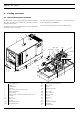
QAS 30 - 45 - 60 Pd 2. Leading particulars 2.1 General description QAS 30 Pd The QAS 30 Pd is an AC generator, built for continuous running at sites where no electricity is available or as stand-by in cases of interruption of the mains. The QAS 30 Pd generator is driven by a water-cooled diesel engine, manufactured by PERKINS. An overview of the main parts is given in the diagram below. The generator operates at 50/60 Hz, 230/240 V in line-to-neutral mode and 400/480 V in line-to-line mode.
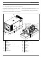
Instruction manual 2.2 General description QAS 45 Pd and QAS 60 Pd The QAS 45 Pd and QAS 60 Pd are AC generators, built for continuous running at sites where no electricity is available or as stand-by in cases of interruption of the mains. The QAS 45 Pd and QAS 60 Pd generators are driven by a watercooled diesel engine, manufactured by PERKINS. An overview of the main parts is given in the diagram below.
QAS 30 - 45 - 60 Pd 2.3 Bodywork Read the instruction manual before use. The alternator, the engine, the cooling system, etc. are enclosed in a sound-insulated bodywork that can be opened by means of side doors (and service plates). To be able to lift the generator by means of a crane, open the door in the middle of the roof to get access to the lifting beam. Indicates the partnumbers of the different service packs and of the engine oil. These parts can be ordered to the factory.
Instruction manual 2.6 Control and indicator panel Qc1001™ 2.6.3 2.6.1 Following pushbuttons are used on the Qc1001™: General description Qc1001™ control panel ENTER: Is used to select and confirm changed settings in the Configuration. H1 P1 R11 P2 R12 P3 30 30 20 P4 UP: Is used to scroll through the display information. This button is also active in Configuration Mode. S4 30 20 400 20 200 10 10 0 10 0 Pushbutton and LED functions 0 0 A1 F4 Qc 1001 A1 F4 ! Appl. 1.00.
QAS 30 - 45 - 60 Pd Following LEDs are used on the Qc1001™: It's possible to scroll through the views, using the UP and DOWN buttons. The scrolling is continuous. 3? If a Special status comes up, the Status Display is shown. If a Warning comes up, the Warning Display is shown. If a Shutdown comes up, the Shutdown Display is shown. ! View 0 3? www.atlascopco.com This view will show the ASW version number.
Instruction manual View 3 (Engine Oil Pressure Display) 5.4bar 00000.7h View 10 (reserved for normal English text) In case that normal English text is selected i.s.o. icons, views 2 & 3 & 4 are changed into this three-row display format. Status Display (pop-up window) 85% This view shows the oil pressure icons. When the English text view is selected, this view will mention: "OIL PRESSURE **.*bar". 00000.
QAS 30 - 45 - 60 Pd Warning Display (pop-up window) 85% 00000.8h In case when a Warning occurs, a pop-up window will automatically be entered for as long as the warning is active, no matter which view is active. The warning icons will be shown (together with a continuous lit alarm LED at the fascia), which is centered at the display. The Warning Display can always be left or entered again by pushing the BACK button.
Instruction manual Shutdown Display (pop-up window) 85% SERVICE TIMER 1 00000.8h In case when a Shutdown occurs, a pop-up window will automatically be entered, no matter which view is active. SERVICE TIMER 2 ; ; This pop-up window will stay present until the unit is put in OFF. ALARM The shutdown icon will be shown (together with a flashing alarm LED at the fascia), which is centered at the display.
QAS 30 - 45 - 60 Pd Configuration Mode View – Service Timer 2 reset V> Setpoint 8)+ – Service Timer 1 reset – Start Prepare Time % "& 8)+ – Unit Menu The Configuration Menu's are pre-programmed! – Unit Type The Configuration Mode is entered by detection of activation of pushbuttons UP and DOWN at the same time for 3s. ! Unit type 2 for QAS 30 - 45 - 60 Pd ! A password will be asked for when an attempt to change a setting is about to be done (user password = “2003”).
Instruction manual 2.6.5 Remote start operation Installation wirings: – X25.1 & X25.2 to be wired for the remote start switch. – X25.3 & X25.4 to be wired for the remote contactor (open/close). 2.6.6 Fail classes All the activated alarms of the Qc1001™ have their own predefined fail class.
QAS 30 - 45 - 60 Pd 2.7 Control and indicator panel Qc3001™ 2.7.3 2.7.1 There are 16 pushbuttons on the display unit. General description Qc3001™ control panel Pushbutton functions ALARM: Shows the active alarm list (up to 30 alarms can be listed). A1 R11 S20 R12 A1 F4 S20 F4 JUMP: Each programmable parameter has a channel number in the menu.
Instruction manual 2.7.5 Qc3001™ Menu Overview AUTO: Allows the user to set the generator in AUTO mode. Main View SEMI-AUTO: Allows the user to set the generator in SEMI-AUTO mode. The display has 4 different lines. The information on these lines can change, depending on which view is used. There are 4 different main views possible: SETUP / S3 / S2 / S1. Setup view TEST: Allows the user to set the generator in TEST mode. To enter the TEST mode, a password needs to be entered.
QAS 30 - 45 - 60 Pd SETUP menu – The fourth line shows the different possible set points. In this example: The control and protection parameters can be programmed according the application. This can be done by scrolling through the setup menu to the appropriate parameter.
Instruction manual This is the described menu flow: The menu flow is similar in the CONTROL SETUP, POWER SETUP and SYSTEM SETUP. ! For more details on the Setup menu we refer to the Qc3001™ User Manual. The JUMP button Instead of navigating through the entire menu, the user can jump directly to the required parameter, if he knows the channel number of that specific parameter. If the JUMP button is pushed the password view will appear. Not all parameters can be changed by the end-user.
QAS 30 - 45 - 60 Pd Protection setup: overview of parameters (for correct values refer to controller) 1090 1100 1110 1120 1130 1140 1150 1210 1220 1230 1240 22 Reverse Power 1091 Setpoint 1092 Delay 1093 Output Relay A 1094 Output Relay B 1095 Enable 1096 Fail Class SERVICE LEVEL -40.0% 0.5 R0 R0 ON Trip + Stop 1250 Gen High Frequency 1 1251 Setpoint (-50.0 ... 0.0) 1252 Delay (0.1 ... 100.0) 1253 Output Relay A (R0 ... R3) 1254 Output Relay B (R0 ...
Instruction manual 1380 1390 1400 1410 1420 VDO 2.2 1381 1382 1383 1384 1385 1386 Setpoint Delay Output Relay A Output Relay B Enable Fail Class SERVICE LEVEL N/A 5.0s R0 R0 OFF Warning 1490 Fuel Level 2 (0 ... 100) 1491 Setpoint (0.0 ... 100.0) 1492 Delay (R0 ... R3) 1493 Output Relay A (R0 ... R3) 1494 Output Relay B (OFF / RUN / ON) 1495 Enable (Warning / Trip / Trip+Stop / Shutdown) 1496 Fail Class (0 / 1 / 2) CUSTOMER LEVEL N/A 20.0s R0 R0 OFF Warning (0 ... 100) (0.0 ... 100.0) (R0 ...
QAS 30 - 45 - 60 Pd System setup: overview of parameters 4010 4020 Nominal Settings 4011 Frequency 4012 Generator Power 4013 Generator Current 4014 Generator Voltage CUSTOMER LEVEL 50Hz 13kW 42A 230V (48.0 ... 62.0) (10 ... 20000) (0 ... 9000) (100 ... 25000) Nominal Settings 2 4021 Frequency 4022 Generator Power 4023 Generator Current 4024 Generator Voltage CUSTOMER LEVEL 50Hz 13kW 42A 230V (48.0 ... 62.0) (10 ... 20000) (0 ... 9000) (100 ... 25000) Transformer Gen-set 4051 Volt. Prim. 4052 Volt.
Instruction manual 4730 4740 4750 4760 4770 4780 2954 2370 00 Start/Stop Cmd. 3 4731 Enable 4732 START/STOP 4733 Day(s) 4734 Hour 4735 Minute CUSTOMER LEVEL OFF STOP 10 10 0 CUSTOMER LEVEL 0000 (0 ... 9999) Start/Stop Cmd. 6 4761 Enable 4762 START/STOP 4763 Day(s) 4764 Hour 4765 Minute 4790 GSM Pin Code (ON / OFF) 4791 Pin code (START / STOP) (0 / 1 / 2 / 3 / 4 / 4910 5 / 6 / 7 /Service 8 / 9 / 10) Timer 1 (0 ... 23) 4911 Enable (0 ...
QAS 30 - 45 - 60 Pd 2.7.6 Passwords 2.7.9 Changing different parameters requires different password levels. Some parameters cannot be changed by the end-customer because of safety reasons. Enables the user to test the generator on a regular basis. The generator will follow a predefined sequence of actions. – No password – User password (default setting "2003") Semi-Auto mode – Service password – Master password Once the password has been entered, the user can change all the accessible set points.
Instruction manual 2.7.10 Standard applications Automatic Mains Failure (AMF) operation In the Qc3001™ module 3 application types can be selected (in channel 4320). A combination of each application type with the running mode results in a specific application. This application is only possible in combination with the Auto mode. If the Semi-auto mode is selected the AMF operation will NOT function! Depending on the application the user has to connect extra wirings to terminal blocks X25.
QAS 30 - 45 - 60 Pd 2.8 Output terminal board The output terminal board is situated below the control and indicator panel. Q1 Q1 X1 X1 S2 S2 S2...... Emergency stop button Push the button to stop the generator in case of an emergency. When the button is pressed, it must be unlocked, by turning it anti-clockwise, before the generator can be restarted. The emergency stop button can be secured in the locked position with the key, to avoid unauthorized use. Q1 .....
Instruction manual 3. Operating instructions ! In your own interest, always strictly observe all relevant safety instructions. Do not operate the generator in excess of the limitations mentioned in the Technical Specifications. Local rules concerning the setting up of low voltage power installations (below 1,000 V) must be respected when connecting site distribution panels, switch gear or loads to the generator.
QAS 30 - 45 - 60 Pd The voltage drop across a cable can be determined as follows: 3 ⋅ I ⋅ L ⋅ ( R ⋅ cos ϕ + X ⋅ sin ϕ ) e = -----------------------------------------------------------------------------1000 e = Voltage drop (V) I = Rated current (A) L = Length of conductors (m) R = Resistance (Ω/km to VDE 0102) X = Reactance (Ω/km to VDE 0102) 3.2.
Instruction manual 3.4.2 During operation Qc1001™ Following points should be carried out regularly: – Check the engine gauges and the lamps for normal readings. ! Avoid to let the engine run out of fuel. If it happened, priming will speed up the starting. – Check for leakage of oil, fuel or coolant. – Avoid long low-load periods (< 30 %). In this case, an output drop and higher oil consumption of the engine could occur.
QAS 30 - 45 - 60 Pd 4. Maintenance 4.1 Maintenance schedule for QAS 30 Pd ! 4.1.1 Before carrying out any maintenance activity, check that the starter switch is in position O and that no electrical power is present on the terminals. Maintenance schedule Service pak Daily 500 hours or yearly 1000 hours - 2912 4410 05 - For the most important subassemblies, Atlas Copco has developed service kits that combine all wear parts.
Instruction manual 4.2 Maintenance schedule for QAS 45 Pd and QAS 60 Pd ! 4.2.1 Before carrying out any maintenance activity, check that the starter switch is in position O and that no electrical power is present on the terminals. Maintenance schedule Service pak Daily 500 hours or yearly 1000 hours - 2912 4411 05 - For the most important subassemblies, Atlas Copco has developed service kits that combine all wear parts.
QAS 30 - 45 - 60 Pd 4.5 Engine oil specifications ! 4.5.2 It is strongly recommended to use Atlas Copco branded lubrication oils. High-quality, mineral, hydraulic or synthesized hydrocarbon oil with rust and oxidation inhibitors, anti-foam and anti-wear properties is recommended.
Instruction manual 4.8 Engine coolant specifications ! The system may be under pressure. Remove the cap slowly and only when coolant is at ambient temperature. A sudden release of pressure from a heated cooling system can result in personal injury from the splash of hot coolant. It is strongly recommended to use Atlas Copco branded coolant. The use of the correct coolant is important for good heat transfer and protection of liquid-cooled engines.
QAS 30 - 45 - 60 Pd 4.9.2 Topping up of coolant – Verify if the engine cooling system is in a good condition (no leaks, clean,...). – Check the condition of the coolant. – If the condition of the coolant is outside the limits, the complete coolant should be replaced (see section “Replacing the coolant”). – Always top-up with PARCOOL EG. – Topping up the coolant with water only, changes the concentration of additives and is therefore not allowed. 4.9.
Instruction manual 5. Storage of the generator 5.1 Storage – Store the generator in a dry, frost-free room which is well ventilated. – Run the engine regularly, e.g. once a week, until it is warmed up. If this is impossible, extra precautions must be taken: - Consult the engine’s operator manual. - Remove the battery. Store it in a dry, frost-free room. Keep the battery clean and its terminals lightly covered with petroleum jelly. Recharge the battery regularly.
QAS 30 - 45 - 60 Pd 6.3 Alternator trouble shooting Symptom Possible cause Corrective action Alternator does not excite Blown fuse. Replace fuse. Insufficient residual voltage. Increase the speed by 15%. No residual voltage. For an instant apply on the + and – terminals of the electronic regulator a 12 V battery voltage with a 30 Ω resistor in series respecting the polarities. After being excited alternator does not excite Connections are interrupted.
Instruction manual 6.4.4 – – – – – – – – Restriction in a fuel pipe. Fault in fuel lift pump. Dirty fuel filter element. Air in fuel system. Fault in atomisers or atomisers of an incorrect type. Fault in cold start system. Engine temperature is too high. Incorrect valve tip clearances. 6.4.5 – – – – High fuel consumption Restriction in air filter/cleaner or induction system. Fault in atomisers or atomisers of an incorrect type. Fault in cold start system. Wrong type or grade of fuel used.
QAS 30 - 45 - 60 Pd 7. Options available for QAS 30 Pd, QAS 45 Pd and QAS 60 Pd units 7.1 Circuit diagrams 7.3 Description of the electrical options The engine control circuit diagrams and the power circuit diagrams for the standard QAS 30, QAS 45 and QAS 60 Pd units: 7.3.1 Unit The “trickle charger” charges the battery completely and is disconnected once the unit starts up.
Instruction manual 7.3.4 Outlet sockets (S) Outlet sockets QAS 30 Pd A brief description of all outlet sockets and circuit breakers provided on the generator is given hereafter: ! Circuit breaker Q1 does not only interrupt the power supply towards X1, but also towards X2, X4, X5 and X6. Make sure to switch on circuit breakers Q1, Q4, Q5 and Q6 after starting the generator when power supply is done by means of X4, X5 or X6. X2 ........
QAS 30 - 45 - 60 Pd 7.3.6 Q2 Q3 Q2 Q4 Q3 Q5 Dual frequency with electronic speed control (DF) The "Dual frequency with electronic speed control" option allows the unit to work at 50 Hz or at 60 Hz with an improved accuracy at constant load. The frequency selection is done by means of switch S12. Q4 Q6 Q6 P1 Q5 R11 P2 R12 20 P3 30 20 30 20 P4 30 S4 400 200 10 X2 X3 X4 X5 10 0 A1 R12 X6 10 0 R11 0 0 F4 Qc 1001 Appl. 1.00.1 ! S20 www.atlascopco.
Instruction manual 7.3.8 Low voltage (LV) The "Low voltage" option allows to run the unit at low voltage (= high current). ! All the cables that are used must be suitable for high current. 7.3.10 Earth leakage relay The “Earth relay” option provides a detector that will trip the main circuit breaker Q1 when an earth fault current is detected. S13 S13 N13 N13 Q1 Q1 X1 X1 X1 Q1......Main circuit breaker X1 N13....Earth leak detector Q1......
QAS 30 - 45 - 60 Pd 7.3.11 IT-relay S2...... Emergency stop button The generator is wired for an IT network i.e. no supply lines of the power supply are directly earthed. A failure in insulation resulting in a too low insulation resistance, is detected by the insulation monitoring relay. ! The generator shall not be operated with other networks (such as TT or TN). Doing so will cause tripping of the insulation monitoring relay. 7.3.
Instruction manual 7.4 Overview of the mechanical options The following "mechanical" options are available for the QAS 30, QAS 45 and QAS 60 Pd units: When using this option, make sure to connect the fuel supply line as well as the fuel return line. Connections to fuellines ought to be air-tight to prevent air from entering the fuel system. Position 1: Indicates that the fuel supply line to the engine is connected to the internal fueltank.
QAS 30 - 45 - 60 Pd 8. Technical specifications 8.1 Technical specifications for QAS 30 Pd units 8.1.1 Readings on gauges Gauge Reading Ammeter L1-L3 (P1-P3) Voltmeter (P4) Below max. rating Below max. rating 8.1.2 Unit A V Settings of switches Switch Function Activates at Engine oil pressure Engine coolant temperature shut down shut down 0.5 bar 105°C 8.1.
Instruction manual Alternator 4) Engine 4) Standard Make IEC34-1 ISO 8528-3 NEWAGE IEC34-1 ISO 8528-3 NEWAGE Model Rated output, class H temp. rise rating type acc. ISO 8528-3 Degree of protection Insulation stator class Insulation rotor class Number of wires BCI 184 H 37.5 kVA BR IP 23 H H 12 BCI 184 H 46.9 kVA BR IP 23 H H 12 ISO 3046 ISO 8528-2 1103A-33G2 27 kW ICXN water direct injection natural aspirated 3 3.3 l mechanical electronic 7.4 l 10.1 l 12 Vdc ISO 3046 ISO 8528-2 1103A-33G2 30.
QAS 30 - 45 - 60 Pd Notes 1) Reference conditions for engine performance to ISO 3046-1. 2) See derating diagram or consult the factory for other conditions. 3) At reference conditions unless otherwise stated. 4) Rating Definition (ISO 8528-1): • LTP: Limited Time Power is the maximum electrical power which a generating set is capable of delivering (at variable load), in the event of a utility power failure (for up to 500 hours per year of which a maximum of 300 hours is continuous running).
Instruction manual 8.2 Technical specifications for QAS 45 Pd units 8.2.1 Readings on gauges Gauge Reading Ammeter L1-L3 (P1-P3) Voltmeter (P4) Below max. rating Below max. rating 8.2.2 Unit A V Settings of switches Switch Function Activates at Engine oil pressure Engine coolant temperature shut down shut down 0.5 bar 105°C 8.2.
QAS 30 - 45 - 60 Pd Alternator 4) Engine 4) Standard Make IEC34-1 ISO 8528-3 NEWAGE IEC34-1 ISO 8528-3 NEWAGE Model Rated output, class H temp. rise rating type acc. ISO 8528-3 Degree of protection Insulation stator class Insulation rotor class Number of wires UCI 224 D 50 kVA BR IP 23 H H 12 UCI 224 D 62.5 kVA BR IP 23 H H 12 ISO 3046 ISO 8528-2 1103A-33TG1 41.3 kW ICXN water direct injection turbo 3 3.3 l mechanical electronic 8l 12.6 l 12 Vdc ISO 3046 ISO 8528-2 1103A-33TG1 48.
Instruction manual Notes 1) Reference conditions for engine performance to ISO 3046-1. 2) See derating diagram or consult the factory for other conditions. 3) At reference conditions unless otherwise stated. 4) Rating Definition (ISO 8528-1): • LTP: Limited Time Power is the maximum electrical power which a generating set is capable of delivering (at variable load), in the event of a utility power failure (for up to 500 hours per year of which a maximum of 300 hours is continuous running).
QAS 30 - 45 - 60 Pd 8.3 Technical specifications for QAS 60 Pd units 8.3.1 Readings on gauges Gauge Reading Ammeter L1-L3 (P1-P3) Voltmeter (P4) Below max. rating Below max. rating 8.3.2 Unit A V Settings of switches Switch Function Activates at Engine oil pressure Engine coolant temperature shut down shut down 0.5 bar 105°C 8.3.
Instruction manual Alternator 4) Engine 4) Standard Make IEC34-1 ISO 8528-3 NEWAGE IEC34-1 ISO 8528-3 NEWAGE Model Rated output, class H temp. rise rating type acc. ISO 8528-3 Degree of protection Insulation stator class Insulation rotor class Number of wires UCI 224 E 60 kVA BR IP 23 H H 12 UCI 224 E 70 kVA BR IP 23 H H 12 ISO 3046 ISO 8528-2 1103A-33TG2 59.3 kW ICXN water direct injection turbo 3 3.3 l mechanical electronic 8l 12.6 l 12 Vdc ISO 3046 ISO 8528-2 1103A-33TG2 69.
QAS 30 - 45 - 60 Pd Notes 1) Reference conditions for engine performance to ISO 3046-1. 2) See derating diagram or consult the factory for other conditions. 3) At reference conditions unless otherwise stated. 4) Rating Definition (ISO 8528-1): • LTP: Limited Time Power is the maximum electrical power which a generating set is capable of delivering (at variable load), in the event of a utility power failure (for up to 500 hours per year of which a maximum of 300 hours is continuous running).
Instruction manual 8.4 Conversion list of SI units into British units 1 bar = 14.504 psi 1m = 3.281 ft 1g = 0.035 oz 1 mm = 0.039 in 1 kg = 2.205 lb 1 m³/min = 35.315 cfm 1 km/h = 0.621 mile/h 1 mbar = 0.401 in wc 1 kW = 1.341 hp (UK and US) 1N = 0.225 lbf 1l = 0.264 US gal 1 Nm = 0.738 lbf.ft 1l = 0.220 lmp gal (UK) t°F = 32 + (1.8 x t°C) 1l = 0.035 cu.ft t°C = (t°F - 32)/1.8 – A temperature difference of 1°C = a temperature difference of 1.8°F. 8.
QAS 30 - 45 - 60 Pd 56 2954 2370 00
Circuit diagrams 2954 2370 00 57
CIRCUIT DIAGRAM .7 .8 U5 X+(F1) XX-(F2) b0 U1 V1 W1 N V1 U1 C V1 400-480V PE 29 12 24 20 V5 (O) 47 46 b0 F2 50 60 U1 U2 U5 U6 V6 V5 W2 W1 W5 W6 V2 a0 9 8 7 1 2 3 4 5 6 X9 A 35 to Circ.Diagr ENGINE Qc3001 - A1.25 a3 37 10 36 11 B a3 a3 a3 27 C 26 12 27 a2 N11 bx0 F1 a6 a3 bx0 8 2 a0 a3 7 1 See Note 2 .F1 28 1 a2 R12 .F2 46 47 R11 a0 Z2 b0 N1 Z2 1 a2 G3 .
CIRCUIT DIAGRAM c8 C H Wire Size x Wire Size y 10mm2 10mm2 Legend 151 to Circ.Diagr ENGINE Ampere-meter 125 U1 F1 a0 a0 126 F2 a0 a0 a0 to Circ.Diagr ENGINE V-meter & Control Module 127 F3 Colour code : aa = 0.5mm 2 0 = black a = 1 mm 2 1 = brown 2 b = 1.5mm 2 = red c = 2.5mm 2 3 = orange d = 4 mm 2 4 = yellow 2 e = 6 mm 5 = green 2 6 = blue f = 10 mm g = 16 mm 2 7 = purple h = 25 mm 2 8 = grey 2 9 = white i = 35 mm 2 j = 50 mm 54= green/yel. k = 70 mm 2 bx = 1.
CIRCUIT DIAGRAM 9822 0992 11/00 Applicable for QAS 30 Low voltage B11 N12 R11 a2 R12 E 12 20 24 D 8 a6 L L 9 8 7 4 5 6 a6 27 a6 5 70 a3 X9 a3 12 5 X9 27 3 C 12 2 50 60 30 a3 5 a3 12 a6 12 (O) 70 X9 C 7 a3 a3 X9 B Z2 a0 12 11 10 1 F1 See Note 2 47 46 a2 N11 A 2 a0 a3 F2 1 35 a0 29 a2 47 46 28 Canopy Cubicle 2 a3 (O) to K7.
.7 V6 V5 V2 V1 V5 bx0 QAS T1 Q1 Wire Size x Wire Size y 30 100/5A 80A 25mm† 16mm† 230V 50Hz U5 U1 V1 W1 V6 141 PE bx0 U1 E Z2 b0 .8 D X+(F1) C b0 U1 B C W6 U1 W5 U2 W2 U5 W1 U6 XX (F2) V1 b0 .Z2 A .F1 .F2 G3 Canopy Cubicle CIRCUIT DIAGRAM 142 c8 to Circ. Diagr ENGINE Ampere-meter 143 c8 c8 T3 to Circ. Diagr ENGINE Ampere-meter C W1 x0 y6 y54 V1 a0 F1 125 x0 U1 x0 V1 U1 c8 a0 F2 126 T2 151 T1 a0 F3 a0 F G a0 C 124 N a6 C to Circ.
CIRCUIT DIAGRAM 9822 0992 18/01 Applicable for QAS 30 - 45 - 60 Qc1001™ 441 b6 a6 2 3 4 13 Canopy Cubicle 17 a2 X25 6 5 Fx Sx B c2 10A b0 X25 1 S20 F4 C 12 38 a0 a3 12 19 18 a3 X25 A to Circ.Diagr POWER X9.441 & X9.442 to Control Module A1 442 2 a6 D Fx F (*) N L1 G MAINS SUPPLY H J c2 a6 a6 a3 7 8 12 12 a3 6 K4 (*)= Connect L2 to X25.1 with 230Vd-systems 1 Plant Contactor Output: 12Vdc, max. 8Adc1 6A 15 Sx=Remote Start/Stop-switch max.
13 CIRCUIT DIAGRAM 17 17 18 X25 a3 X25 19 a3 A c8 A 2 to Circ.Diagr POWER Current Transfo T1-T3 c8 14 D c8 P3 S2a 1 A P2 b2 a2 C 141 b2 142 B P1 143 a2 17 A E 151 b3 F 124 c8 128 11 7 a0 12 3 6 a3 4 129 5 1 8 to Circ.
CIRCUIT DIAGRAM Canopy Cubicle 9822 0992 19/01 Applicable for QAS 30 - 45 - 60 Qc3001™ A B 1 2 3 a0 a0 4 5 a0 a0 6 7 445 444 443 442 446 447 125 a0 a0 9 11 3 NO A1 a0 a6 Com a2 12 17 17 a2 NC b2 to Circ.
a0 a0 c8 c8 c8 c8 a3 a3 a3 a6 b6 a6 b0 a0 a0 a0 a0 a0 a0 to BATT- a3 a6 a6 X25 10 X25 a2 a3 a3 Fx 5 6 Fx Common for VDO-inputs (0 Vdc) Relay Output 3 NO 6A 250mA 250mA 250mA N L1 L1 L2 L3 MAINS SUPPLY (3P+N+PE) Customer's Installation (see Instruction Manual) 9 Sx Sx=Remote Start/Stop-switch Common for Relay Outputs Relay Output 2 NO 6A 8 Com Fuel Level (VDO) Relay Output 1 NO PE 7 to Plant Contactor A2 <-- Fx 4 to Plant Contactor A1 <-- Fx 3 Input
CIRCUIT DIAGRAM & A B C ) ) D ) ) ) ) ) ) A A ) % ) & & ) % ) ) % $ $ $ $ % 23 & A A & A A & & * & !" +,-. ,) - /0 1. 23 23 % % * 23 $ / ) ) -5<956. 5;5.
CIRCUIT DIAGRAM $ % "5' " + ' ? A + ' ? @ + 6/:25 6 5 6 > 6 > //:25 //5 2 > 6 > D *D /#2D > /D *D ! D *D & 2/:25 25 2/ > 2 > D *D D 2/:25 115 2/ > 2 > D *D #2D > D *D D *D #2D > D *D D *D 1D > 1D *D @ & D *D 6D > 2D *D % 1 0/ // 1 0 #- % 34 1 A B C ? 12 6/ 0 5 ( 0 > % D *D /D > 6D *D %D *D 6D >
CIRCUIT DIAGRAM 9822 0992 21/01 Applicable for QAS 45 - 60 Low voltage * ' " " " ! ! " 345 ! ! ! % , :# ; 1 1 + % 267 8 9 " " ' -" A B C D E F G - - < # - 1 345 ! H I J !" ' " 0 -& '
# + ), >)7 ), >)7 = 0 = 0 = 0 = 0 0 0 0 0 11< 11< 11< 11< 2 > 11< 11< 11< 11< ! ! ! ! 89$ : !2 67 ! ! ! " " ;9$ : 0> " ! " #$ " #$ " # # / # " # A B C D E F G %&' (") * CIRCUIT DIAGRAM & ), #-) , ./ . 01' , 21 , + + + & ), #-) , ./ .
Printed in Belgium 07/2005 - 2954 2370 00 www.atlascopco.
Instruction Manual for AC Generators QAS 30 - 45 - 60 Pd