
Instruction manual
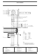
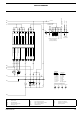
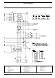


CIRCUIT DIAGRAM
2954 2370 00 63
P1-3 Amperemeter S4 Voltmeter change-over switch V2 Diode
P4 Voltmeter S6 Low coolant level switch X10 Connector wire harness
R2 Excitat. resistor 47 Ohm
S8 High coolant temperature switch
X25 Customer's terminal strip
S2a Emergency stop S9 Low oil pressure switch Y1 Fuel stop solenoid
(S2b: see Power Circuit) S20 ON/OFF/Remote switch
5
1
8
10
4
6
2
12
11
7
3
9
S4
A
A
A
V
a2
17
a6
12
4
X25
3
X25
2
X25
1
X25
to Circ.Diagr POWER
a3
17
5
a3
12
a6
M
M6
2
2
2
2
2
2
2
2
2
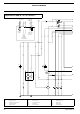
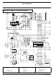
Wire size : Colour code :
Legend
aa = 0.5mm
a = 1 mm
b = 1.5mm
c = 2.5mm
d = 4 mm
e = 6 mm
f = 10 mm
g = 16 mm
j = 50 mm
0 = black
2 = red
3 = orange
4 = yellow
5 = green
6 = blue
7 = purple
8 = grey
54= green/yellow
c3
K5
b5
K4
c1
K1
Position of Relay Cont.
to Circ.Diagr POWER
Fuses F1-F3
a0
128
a0
129
a6
124
a0
127
a0
126
a0
125
a3
10
a3
10
a3
9
a3
9
to Circ.Diagr POWER
H1
a3
10
a3
9
a3
11
B9 B8
a3
8
to Circ.Diagr POWER
Current Transfo T1-T3
c8
151
c8
143
c8
142
P3
P2
c8
141
P1
a3
18
a3
19
a3
19
a3
18
a0
38
a2
13
a2
13
a2
17
a2
17
b3
14
a0
129
a0
128
a0
129
a0
128
a3
5
a3
5
a0
129
a0
128
a3
5
a3
5
a6
12
a6
12
a3
14
a3
14
b3
14
b2
17
a2
17
b2
17
a3
15
a6
22
a6
12
a6
12
a6
12
a3
11
a3
5
a3
4
a3
11
a3
5
P4
S2a
a6
12
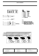
CAN-H
GND
CAN-L
General Fail
Fuel Control Relay
Com
Com
A1
NO
NO
0 Vdc (Batt-)
Load Contactor
Preheat Relay
Common for Relay Outputs
262524 27
12/24 Vdc (Batt+)
23
Generator voltage L1
2119
Generator Voltage L2
36
NO
32
NO
NOStart Relay Output
3533 34
Input
Input
Input
Input
Input
Common (12Vdc)
High Coolant Temperature
Low Oil Pressure
W/L Input
Remote Start
Start/Stop
Low Coolant Level
Input
14 161512 13 17 18
Input
Input
Input
Coolant Temp.(VDO)
Oil Pressure (VDO)
6754312
Engine CAN-bus Interface
Fuel Level (VDO)
Common for VDO-inputs (0 Vdc)
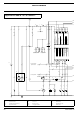
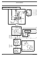
C3
C3
X10
Cubicle
Canopy
B5
B5
X10
B4
B4
X10
A5
A5
X10
C1
C1
X10
A4
A4
X10
C2
C2
X10
a6
12
a3
4
+
-
A
B7
D
C
a6
12
K1
a3
5
a6
12
Y1
A
B
C
D
E
F
G
H
K
L
M
N
J