A U T O M A T I C T R A N S M I S S I O N R E M O T E S T A R T E R AS-1725 SH Installation Guide Notice The manufacturer will accept no responsibility for any electrical damage resulting from improper installation of the product, be that either damage to the vehicle itself or to the Unit. This Unit must be installed by a certified technician using all safety devices supplied.
Table of Contents Table of Contents ......................................2 Introduction................................................2 Included in the Kit ......................................2 Installation Points to Remember................3 Harness Description ..................................4 Flashing the Hood Pin Switch....................9 The Programming Assistance Button ......10 Programming the Transmitter..................10 Before you Proceed.................................
x 1 – User Guide The plug-in Valet button is not included with this Remote Car Starter. INDUSTRY CANADA USER NOTICE: Operation is subject to the following two conditions: (1) this device may not cause interference, and (2) this device must accept any interference, including interference that may cause undesired operation of the device.
Wiring a Clutch Bypass and a Transponder Module to the GROUND OUT WHEN RUNNING wire: At the junction point, where the GROUND OUT WHEN RUNNING wire “splits” and connects to each device, a diode is inserted on each of these lines. Multiple or separate Door pin Connections: When joining all Door Pins together to the Door Pin input wire of the Remote Car Starter unit, each wire must be isolated with a diode to prevent feedback.
E ORANGE F GREEN This wire will power the Heater Blower Motor. Usually connected to the Accessories wire of the vehicle. The source wire must have power with the Ignition Key in the IGNITION ON (RUN) position only (no power in the CRANK position). (+) Accessories Warning: at the Ignition Switch of certain vehicles, there may be output (30 A) more than one Ignition wire for powering the Heater Blower Motor. Use the 5th relay (Pin F) and extra relays to power up any extra Ignition wires if necessary.
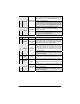
12-Pin Accessories Harness Wire Colour 1 BLUE 2 BROWN 3 GREEN 4 WHITE / BROWN 5 WHITE / GREEN 6 BLUE / WHITE 7 WHITE / ORANGE 8 ORANGE P. 6 Function Description 500 mA negative output. This output can be used to control the (–) Trunk / Trunk release (1-sec. pulse), or it can be set to operate as a AUX 3 output constant output as long as the TRUNK button is held pressed (for Sunroof or Window closure) (–) Lock Programmable 500 mA negative output: 1/10-sec., 7/10-sec. or 4output sec.
9 PURPLE (–) External Trigger 10 WHITE (–) Ground Out When Running 11 GREY (–) N/A AS-1725 SH Installation Guide The External Trigger wire can be used for remote-starting the vehicle with an external device. When the vehicle is running, triggering this input will activate Idle Mode. The External Trigger wire can also be used to operate as a negative trigger with the Trunk Pin-switch, the Key Sense wire or the Door Pin-switch: Option 1 Connects to Negative Trunk Pin.
In Diesel Mode, this positive input will monitor the Glow Plug Light: it will wait for up to 18 seconds until the Glow-plug Light goes out before allowing the Remote Car Starter to proceed to cranking the Engine. Connect to the side of the Glow-plug Light which is positive when the Light is on. Note: the Remote Car Starter will nevertheless proceed to cranking the Engine if the Glow-plug Light is still on after the 18sec. delay (25 sec. when the Run Time is set to 30 min.). 12 P.
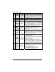
2-Pin Harness Wire Colour Function 1 BLUE/ WHITE (–) N/A 2 YELLOW (–) Parking Light output Description This pin is not used. Leave it empty. 500 mA negative Parking Light output Note: Ensure that the voltage does not vary when the dimmer control switch is turned up or down. If this is the case, it is not the right wire. There is a also a positive Parking Light output. Only one of these two different outputs needs to be connected.
Remember: Once the Parking Lights are ON (solid), you have up to 20 seconds to select a sub-menu. If you do not select a sub-menu within 20 seconds, the Remote Car Starter will exit Programming Mode and you will have to flash the Hood Pin switch once again. The Programming Assistance Button (A.k.a. the PAB.) Mounted on the Remote Car Starter, this button can be used from within the vehicle instead of the Hood Pin switch in the Engine compartment.
To program a Transmitter on the second vehicle for Multi-car Operation, you must press the TRUNK and LOCK buttons simultaneously (instead of LOCK or UNLOCK) in step 2 of the Transmitter code-learning procedure: Entering Programming Options Mode The Remote Car Starter is equipped with three custom programming Modes that allow the installer to custom-fit the system outputs according to installation requirements. The Programming Options are designed to facilitate interfacing with all vehicle types.
Programming Options MODE 1 * INDICATES DEFAULT SETTING FUNCTION 1 – Ignition-controlled Door Locks OPTION 1* OPTION 2 OPTION 3 OPTION 4 Ignition Lock DISABLED Ignition Lock ENABLED Ignition UNLOCK ONLY Ignition LOCK ONLY FUNCTION 2 – Secure Lock OPTION 1* OPTION 2 OPTION 3 OPTION 4 Secure Lock DISABLED (1-sec. Disarm pulse) Secure Lock ENABLED in Smart Mode Secure Lock DISABLED (1/2-sec.
OPTION 2* OPTION 3 Ignition Valet ENABLED Ignition Valet ENABLED MODE 3 * INDICATES DEFAULT SETTING FUNCTION 1 – Home Valet TM OPTION 1 OPTION 2* OPTION 3 Home Valet ENABLED Home Valet DISABLED Home Valet DISABLED FUNCTION 2 – AUX 3 / Zone 3 Programming OPTION 1 OPTION 2* OPTION 3 1-sec. output when TRUNK button is pressed for 3 sec.
of certain Ignition systems are sometimes too low or too high for the Remote Car Starter, causing failed start-ups at various temperatures. 1. Flash the Hood Pin switch (see Table 1) – The Parking Lights will stay ON for up to 20 seconds. – Before the lights go out: 2. Press and hold the Brake Pedal, – And simultaneously press the LOCK and UNLOCK buttons on the Transmitter: – The Parking Lights will flash 4 times. – Release the Brake Pedal. 3.
a. To increase the Horn pulse by 3 ms, press the LOCK button. b. To decrease the pulse by 3 ms, press the UNLOCK button. c. To increase the pulse by 10 ms, press the START or STOP button. d. To decrease the pulse by 10 ms, press the TRUNK button. 5. To save the new settings: press LOCK and UNLOCK. If 3 chirps are returned the new settings have been saved. Table 7: Adjusting Chirp Duration Otherwise close the Hood to cancel the changes.
Closing Up Use tie-wraps or screws to properly secure the Remote Car Starter and keep the wiring away from any moving parts such as the Parking Brakes or Steering Column Shafts. Mount all switches in good and accessible locations where they do not risk getting kicked or hit accidentally. Most comebacks are the result of misunderstandings about how a product works or performs. Take the time to properly explain all functions and features to the customers before they leave the premises.
Secure Lock This feature allows the Remote Car Starter to control certain OEM factory Alarm systems without requiring the use of other wires for disarming the OEM Alarm. (Namely, this feature is designed for OEM systems which use the factory Lock wire to arm the Alarm and the Unlock wire to disarm it.) Standard Secure Lock If this Option is selected, upon receiving a remote START signal, Secure Lock will UNLOCK the Doors (disarming the factory Alarm); 1/2 sec.
x x x Active Arming: the Starter Kill will not arm automatically. Press the LOCK button to arm and the UNLOCK button to disarm it. Passive Arming: the Starter Kill will arm automatically if it is not armed by remote within a 60-sec. delay. Press UNLOCK to disarm. Passive Arming with 3-minute timeout: the Starter Kill will arm automatically after 3 minutes.
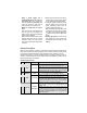
Start Failure Codes through the Parking Lights 1 x = No Start 3 x = Hardware Reset 4 x = Brakes 5 x = No Tach Cut-off 6 x = Hood 7 x = Engine Running, no Ignition detected, or Tach before Start Note: “x” stands for one flash of the Parking Lights Diagnostics – Parking Light Flash Table Flashes 1 2 3 4 5 6 Description x x x x x x x x x x x x x x x x 8 10 1 – pause – 2 x x x ON solid x x 2 – pause – 2 ON 2 sec. ON 3 sec. ON 4 sec. ON 25 sec. Irregular x x x x x Doors locked, Starter Kill armed.
Constant flashes up to 30 sec. P. 20 x Panic Mode is triggered.