
Owner`s manual


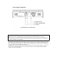
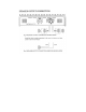
1. RCA Line Output Jacks
Full range output from channel L+R inputs is provided at Line Out Jacks and its output frequency can
be adjusted by 3way x-over (HP/FULL/LP.BP) with line out switch.
2. RCA Line Input Jacks
It allows left and right inputs to be connected to the amplifier using RCA plugs.
3. Balanced Input
Accepts line level balanced input, in the 0.4V to 8V range.
4. Input Level Control
It allows for the adjustment of the gain of both channels to match the output level of the source. In
addition, it allows to adjust from 0.2V to 9.0V when using unbalanced inputs, and from 0.4V to 18V
when using balanced input.
5. High Pass Variable Controls
Adjust the crossover frequency of the High Pass output only, from 10Hz to 4.0KHz.
6. Low Variable Controls
Adjust crossover frequency of the LOW Pass output only, from 40Hz to 4.0Hz.
7. Subsonic Filter
The subsonic filter low pass frequency is fully adjustable from 10Hz to 150Hz, with rolloff of
12dB/Octave in the low pass stereo mode, and 24dB/Octave in the low pass mono mode, to form a
bandpass filter. The higher frequency of 150Hz was chosen, to allow a 2 channel a amplifier to be used
as a midbass or midrange amplifier also.
8. Bass Boost Controls
The bass EQ control wil produce up to +18dB boost at 40Hsfor that extra bass punch.
9. Amplifier X-over switch/Line outs X-over switch
a) LP/P position: Allows for the control of the low pass frequency range (10Hz-4.0KHz) by using the
Low Variable Control, and allows Band Pass with adjustment of Low pass variable & Subsonic
variable controls.
b) Full position: Allows for full range pass through.
c) HP position: Allows for the control of the high pass frequency range (10Hz-4.0Kz) by using the
High Variable Control.
10. Remote control Jacks
These jacks are for use with remote control only. Both jacks are connected together to allow the Daisy
chaining of multiple amplifier to Remote Control Accessory. The low pass signal only will be
controlled.
11. Power LED
It indicates when amplifier is on and no fault exists.
12. Diagnostic LED
It illuminates when fault condition exists, and amplifier immediately shuts down. If illuminated, turn
amplifier off, check for shorted speaker leads and DC noise from RCA input and attempt to re-power
amplifier. When amplifier overheats and thermal protection circuit shuts amplifier off, LED does not
illuminate.
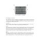
13. Power connection
Connects +12VDC power wire from the battery and also connects ground wire from a suitable ground
point on the chassis.
14. Remote connection
Connects the control wire which allows the amplifier to be turned on and off by the radio cassette
player.
15. Speaker Terminal
It allows the connection of speakers to the amplifier.
16. External Fuse
It offers external fuse to connect from battery directly. AMX200.2: 80A.