Interactive Fire Alarm System Release 3 Installation Handbook Fire Alarm Control Panel, BS-310/320 Controller, BC-320 Protecting life, environment and property... 116-P-ASAFE-FA/DE, Rev.
COPYRIGHT © This publication, or parts thereof, may not be reproduced in any form, by any method, for any purpose. Autronica Fire and Security AS and its subsidaries assume no reponsibility for any errors that may appear in the publication, or for damages arising from the information in it. No information in this publication should be regarded as a warranty made by Autronica Fire and Security. The information in this publication may be updated without notice.
Table of Contents 1. Introduction .......................................................................6 1.1 1.2 1.3 1.4 1.5 1.6 About the Handbook.......................................................................... 6 The Reader ....................................................................................... 6 Reference Documentation................................................................. 7 Environmental Requirements ............................................................
2.7 2.8 2.6.1 External AUTROLON Cables.................................................. 29 2.6.2 Internal AUTROLON Cable..................................................... 29 Internal Cable Connections - Overview............................................. 30 Connections for Temperature Compensated Battery Charging Voltage .............................................................................................. 32 2.8.1 Introduction .................................................................
8. Reader’s Comments .........................................................61 Installation Handbook, AutroSafe Interactive Fire Alarm System, Release 3, 116-P-ASAFE-FA/DE, Rev.
Introduction 1. Introduction 1.1 About the Handbook This handbook is intended to provide all necessary information for the installation of the AutroSafe Fire Alarm Control Panel (BS-310/320) and the Controller BC-320. It also gives detailed information on connections to the network (AUTROLON) and guidelines for the installation and addressing of loop units.
Introduction 1.
Introduction 1.4 Environmental Requirements The equipment complies to environmental conditions of IEC-721-3-3 class 3k5. Ambient temperature:-5 to +40 C Degree of protection:IEC-529/IP30 1.
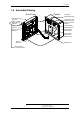
Introduction 1.6 Assembly Drawing Front Panel LON Interface EAU-310 Cabinet Connection Module BSF-310B Display Board BSR-310 Loop Driver or I/O Modules (on top of Power and Comm. Module) Processor Board EAC-300 Communication Module BSL-310 Operator Board BSZ-310 Power Module BSS-310A/02 Power Supply BSS-103/01 Battery Cover Printer BUP-310 Battery Shelf (Not included in Controller, BC-320) Installation Handbook, AutroSafe Interactive Fire Alarm System, Release 3, 116-P-ASAFE-FA/DE, Rev.
Mounting Mounting 1.7 Introduction This chapter deals with the following mounting alternatives: Surface mounting Flush mounting in a wall For surface mounting and flush mounting in a wall, a stand-alone cabinet is used. 1.8 Location The Fire Alarm aControl Panel must be located in, or near by, the entrance. Both the Fire Alarm Control Panel and the Controller must be placed according to local regulations and in consultation with the fire brigade. 1.
Mounting 1.10 Cabinet Dimensions The cabinet (Fire Alarm Control Panel / Controller) has the following dimensions: (cabinet) (front) (cabinet) (front) (Ref. BS-1109) Installation Handbook, AutroSafe Interactive Fire Alarm System, Release 3, 116-P-ASAFE-FA/DE, Rev.
Mounting 1.11 Surface Mounting 1.11.1 Removing the Front Panel All the internal units within the rear cabinet are fastened to a mounting plate. The cabinet is delivered with the front panel fastened to the cabinet. Unscrew the 2 screws on the top and the bottom on the right hand side of the front panel. Lock screw Lock screw Open the front panel. Installation Handbook, AutroSafe Interactive Fire Alarm System, Release 3, 116-P-ASAFE-FA/DE, Rev.
Mounting Disconnect the ribbon cable(s) between the front panel and the cabinet by removing the connector on the BSF-310B board. Ribbon cable connection Unscrew the 4 wing nuts on the right and left hand side of the cabinet, then close the front panel, and remove the front panel from the cabinet . Front Panel wing nuts Installation Handbook, AutroSafe Interactive Fire Alarm System, Release 3, 116-P-ASAFE-FA/DE, Rev.
Mounting 1.11.2 Mounting the Cabinet The cabinet has 5 moun7ting holes located at the rear. The upper holes are of key-hole-type. Consult the illustration above, and do the following: Mark and drill all the holes according to the illustation. Partly fasten the upper screws. Hang the cabinet onto the upper screws. Partly fasten the bottom screws. Tighten all screws. Installation Handbook, AutroSafe Interactive Fire Alarm System, Release 3, 116-P-ASAFE-FA/DE, Rev.
Mounting 1.11.3 Cable Inlets / Outlets Note that two gland plates are fitted to the cabinet, one with predrilled holes and one blank. When feeding the cables, use whichever is appropriate. Entry should always be from top as bottom entry is restricted, particularly if batteries are fitted. The illustration above shows the positioning and dimensions of the cable inlets. Feed all the cables into the cabinet from the top through the suitable cable inlets. Make sure that the cables are fastened properly.
Mounting 1.11.5 Mounting the Batteries Unscrew the screw as shown on the illustration below. Lift the lower part of the cover off the bottom slot and remove the battery cover. Screw Battery Cover Place the batteries in their position as shown, then reassemble the battery cover. 1.11.6 Reassembling the Front Panel When all the necessary cable connections are done, reassemble the front panel. Open the front panel. Tighten the 4 wing nuts on the right and left side inside the cabinet.
Mounting Wing nuts Ribbon cable connection Lock screw (front door) Lock screw Installation Handbook, AutroSafe Interactive Fire Alarm System, Release 3, 116-P-ASAFE-FA/DE, Rev.
Mounting 1.12 Flush Mounting in a Wall 1.12.1 Removing the Front Panel All the inside units in the cabinet are fastened to a mounting plate. The cabinet is delivered with the front panels fastened to the cabinet. Follow the procedure described in chapter 2.5.1; unscrew the 2 screws on the top and the bottom on the right hand side of the front panel and open it. disconnect the ribbon cables between the front panel and the cabinet by removing the connector on the BSF-310B board.
Mounting 1.12.3 Flush Mounting Before Construction of the Wall If a flush mounting is planned before construction of the wall, the cabinet - without the inside units and front panel - can be used as a casting frame. WARNING: To avoid deformation, make sure that the cabinet is supported inside before concreting. Installation Handbook, AutroSafe Interactive Fire Alarm System, Release 3, 116-P-ASAFE-FA/DE, Rev.
Mounting 1.12.4 Cut Out Dimensions The illustration below shows the cabinet’s cut out dimensions. The dimensions given include space for the cover frame, but not for the required free space of minimum 50 mm on the top / bottom of the cabinet. 1.12.5 Mounting the Cabinet The cabinet has 4 mounting holes located on the left and right flange. Consult the illustration above, and do the following: Mark and drill all the holes according to the illustration.
Mounting 1.12.7 Cable Inlets / Outlets Feed all the cables into the cabinet from the rear through the suitable cable inlets (refer to chapter 2.5.3). 1.12.8 Cable Connections For detailed information on cable connections, refer to chapter 3 in this manual. 1.12.9 Mounting the Batteries Follow the instructions in chapter 2.5.5. 1.12.10 Reassembling the Front Panel Follow the instructions in chapter 2.5.6. 1.12.
Internal Cable Connections 2. Internal Cable Connections 2.1 Introduction The Fire Alarm Control Panel / Controller is customized according to each specific delivery. Most of the internal cabling is already done (see Cable Connections - Overview), as the control panel will always be delivered from the factory with the mandatory internal I/O modules; Power Module BSS-310 and the Communication Module BSL-310 installed.
Internal Cable Connections 2.3 Location of Fuses 2.3.1 Fuses on Power Supply, BSS-103A/02 Remove the fuses F1 and F2 on the Power Supply. Do not replace the fuses until commissioning of the system. ! POWER OFF! Fuse No. Size Type Slow/Fast Protecting F1 F2 F3 2A 6,3 A 1A T2AH/250V AC F6,3AH/250V AC T1AL/250V AC Slow (T) Fast (F) Slow (T) Mains Battery External 24V DC F3 F2 F1 Remove fuses F1 and F2. Do not replace the fuses until commissioning of the system.
Internal Cable Connections 2.3.2 Fuses on Connection Module, BSF-310B Fuse No. Size Type Slow/Fast F1 F2 F3 F4 3,15 A 4,0 A 2A 2,5 A T3,15AL/250V AC T4AL/250V AC F2AL/250V AC T2,5AL/250V AC Slow (T) Slow (T) Fast (F) Slow (T) Protecting Charger Circuit Battery I/O Power Battery / External 24V F1 F2 F4 F3 Installation Handbook, AutroSafe Interactive Fire Alarm System, Release 3, 116-P-ASAFE-FA/DE, Rev.
Internal Cable Connections 2.4 Shielding and Earthing 2.4.1 Introduction Due to requirements in EN54 and generic EMC-requirements, it is very important to keep in mind how to make earthing and shielding of cables when installing. 2.4.2 Definitions Protective Earth Termination point to the external protective earth. In AutroSafe this is the connection at the BSS-103A/02 block terminal (terminal 1).
Internal Cable Connections Protective Earth ! In the fixed mains wiring to the panel a two-pole disconnect device must be provided to disconnect the equipment from the power supply when servicing is required. Normally, this switch is a two-pole automatic fuse located in the fuse terminal box at the premises. This fuse location must be marked "Fire Alarm System".
Internal Cable Connections 2.5.2 Connecting the Batteries to Connection Module and Power Supply Schematic outline inside cabinet - Front view Connection Module BSF-310B Power Supply BSS103A/02 Batteries 24V/12Ah NOTE! The illustration below gives an overview of the connections from the Connection Module to the Power Supply and to the batteries. The connection of the batteries is done during commissioning. Until then, do not connect the batteries.
Internal Cable Connections + + - - + - Power Supply - - + - + + 24V / 12Ah Battery Installation Handbook, AutroSafe Interactive Fire Alarm System, Release 3, 116-P-ASAFE-FA/DE, Rev.
Internal Cable Connections 2.6 Connecting the Network Cables (AUTROLON) 2.6.1 External AUTROLON Cables Note that the polarity of the external AUTROLON cables has no importance. Likewise, incoming and outgoing external AUTROLON cables can be freely connected to either LON-A or LON-B (see drawing on next page). For documentation purposes, however, we recommend that output is connected to A and input is connected to B. In high-current environments (power plants, electrical machinery etc.
Internal Cable Connections 2.7 Internal Cable Connections - Overview Watchdog output External AUTROLON cables Connection Module BSF-310B Internal AUTROLON cable to LON Interface board EAU-310 Watchdog output (X4-2 / X4-3): Normal open.
Internal Cable Connections NOTE: 10 9 8 7 6 5 4 3 2 1 Connector 8 + 7 T 6 5 + 4 230V 3 2 1 Protective Earth Neutral 230V +24V DC to battery 0V Test External 24V Output 10 9 8 7 6 5 4 3 2 1 Screw Terminals on Power Supply BSS-103A/02 The following internal cable connections are already done when the product leaves the factory: Power Module BSS-310: A small ribbon cable is used between the Power Module and the Power Supply BSS-103A/02.
Internal Cable Connections 2.8 Connections for Temperature Compensated Battery Charging Voltage 2.8.1 Introduction The Power Supply BSS-103A/02 in the Fire Alarm Control Panel BS310/320 / Controller BC-320 is provided with a temperature sensor for temperature compensated battery charging voltage. The internal connections to the sensor is already done when the product leaves the factory. The cable with the sensor has to be taped to the battery cover bracket.
Internal Cable Connections 2.8.2 Connecting the Cable to External Temperature Sensor When a solution with external battery connection is used, the sensor must be removed from the Power Supply BSS-103A/02. A 3m cable must then be connected between the Power Supply BSS-103A/02 in the Fire Alarm Control Panel / Controller and the external temperature sensor mounted on a connector in the Battery Cabinet SY-310. The cable for this purpose is delivered with the battery cabinet.
Installing I/O Modules 3. Installing I/O Modules 3.1 Introduction This chapter provides information on the mounting and removal of I/O modules. Note that the internal Power Module (BSS-310) and the Communication Module (BSL-310) are already mounted in a fixed position when the product leaves the factory (refer to 1.5). Installation Handbook, AutroSafe Interactive Fire Alarm System, Release 3, 116-P-ASAFE-FA/DE, Rev.
Installing I/O Modules 3.2 Front View of I/O Module Installation Handbook, AutroSafe Interactive Fire Alarm System, Release 3, 116-P-ASAFE-FA/DE, Rev.
Installing I/O Modules 3.3 Mounting / Removing I/O Modules 3.3.1 General Note! Make sure the mains power is OFF! Note: The Power Module (BSS-310) must always be mounted first on the rail - at the bottom - before any other modules. The Communication Module (BSL-310) is then mounted on top of the Power Module. All other modules can be mounted in arbitrary order on top of these two modules.
Installing I/O Modules 3.3.3 Removing Unplug the connection block. Use a screwdriver to carefully lift the topmost module upwards (1) until the connector between the modules is free. Use the screwdriver to slightly bend the left side of the fastener towards left (2) until it loosens, then remove (3) the module. If necessary, continue removing the next one in the same way. 1 2 3 3.3.4 Before Connecting Cables Before connecting cables, make sure that the mains power is not connected.
Installing I/O Modules 3.5 Power Module, BSS-310 The I/O module has the following connections: Screw Terminal no.
Installing I/O Modules 3.6 Communication Module, BSL-310 Connector on ribbon Cable 1 To Connection Module BSF-310B 1 2 3 4 5 6 7 8 9 10 Connector on ribbon Cable 2 To Power Module BSS-103A/02 1 2 3 4 5 6 Signal INT RS_GND TX RS_GND N.C. (GND) RS_GND RX RS_GND CTS RS_GND Signal TEST N.C. N.C. GND MAINS_OK N.C.
Installing I/O Modules 3.7 Loop Driver Module, BSD-310 / BSD-311 Screw Terminal no. 1 2 3 4 5 6 7 8 9 10 Signal OUT + (+24V) OUT - (0V) Shield IN + IN Shield F/S + F/S Chassis Chassis Green indicator, H5. Communication indicator that gives a pulsing green light during traffic. Red indicator, H1. Fail_Safe indicator that gives a steady red light if a communication failure occurs, i.e. the system does not respond to an alarm.
Installing I/O Modules 3.8 Output Module, Monitored, BSB-310 Screw Terminal no.
Installing I/O Modules 3.9 Output Module, BSJ-310 Screw Terminal no. 1 2 3 4 5 6 7 8 9 10 Signal OC1 OC2 OC3 OC4 OC5 OC6 OC7 OC8 24 VBAT Output Chassis Front view when mounted on rail Screw terminal 10 Screw terminal 1 Terminal 9 + Output +24V External terminal list Output 1 Output 8 Maximum 100 mA Schematics + 24V Output 9 Output 1-8 0V_BAT Installation Handbook, AutroSafe Interactive Fire Alarm System, Release 3, 116-P-ASAFE-FA/DE, Rev.
Installing I/O Modules 3.10 Input Module, Monitored, BSE-310 Screw Terminal no.
Installing I/O Modules 3.11 Input Module, BSE-320 Screw Terminal nr. 1 2 3 4 5 6 7 8 9 10 Signal IN1 IN2 IN3 IN4 IN5 IN6 IN7 IN8 n.c. INx-power supply Common source to all inputs (+) Schematics Installation Handbook, AutroSafe Interactive Fire Alarm System, Release 3, 116-P-ASAFE-FA/DE, Rev.
4. Larger Distributed Systems 4.1 AUTROLON Rings with Cable Lengths >1km The maximum length of the AUTROLON ring without AUTROLON Boosters is 1km. AUTROLON Boosters (BSL-325) are required if the AUTROLON cable is more than 1km in length. The maximum length of a total AUTROLON ring with Boosters is 2,8 km. 4.2 Limitations when using AUTROLON Boosters The maximum length of a total AUTROLON ring with Boosters is 2,8 km. Boosters must be evenly spread round the AUTROLON ring.
4.3 Overview - Cable Connections Installation Handbook, AutroSafe Interactive Fire Alarm System, Release 3, 116-P-ASAFE-FA/DE, Rev.
4.4 Connections to the AUTROLON Booster BSL-325 Front view when mounted on rail Screw terminal 10 Indicators H8 H7 H6 H5 H4 H3 H2 H1 Screw terminal 1 The BSL-325 module has the following connections: Screw Terminal no.
Interfacing AutroMaster_5000 5. Interfacing AutroMaster_5000 5.1 General The example below shows part of a larger AutroSafe system connected to an AutroMaster 5000 Colour Graphic System on the top level. The Local Operating Network (AUTROLON) is installed as a ring loop. A high-level bus based ethernet, LAN, can be used between the different work stations in the AutroMaster 5000 system. The AUTROLON is connected to the workstations.
Interfacing AutroMaster_5000 5.2 Connections - Overview The interface of the AutroMaster 5000 requires the use of the Ethernet Communication Board, EAU-330. The Ethernet Communication Board, EAU-330 is mounted onto the Processor Board EAC-300 inside the Fire Alarm Control Panel BS-310, or on the top of the LON Interface Board (EAU-310/B) inside the Fire Alarm Control Panel BS320 or Controller BC-320. The connection can be done via a HUB, or directly to an AutroMaster.
Interfacing AutroMaster_5000 The Ethernet Communication Board, EAU-330 with a Patchcable connected. Patchcable 5.3 Application with several AUTROLON rings 5.3.1 General AutroMaster 5000 is used as the top level system. AutroMaster 5000 enables a two-way communication with both AUTROLON rings and monitors the entire system. NOTE: The communication is not possible through AUTROLON rings by use of AutroMaster 5000.
Interfacing AutroMaster_5000 detection zone with an appropriate text (for example, Fire, block A2, third floor). The transfer of control functions is done similarly. By means of the configuration tool, the DZ for FAI on AUTROLON ring 1 must be connected to FPE or alarm output for AUTROLON ring 1. Note that if the system is configured to, for example, control one output, the current software version does not allow this unless an alarm is shown on panels on AUTROLON ring 1.
Interfacing AutroMaster_5000 5.3.
Interfacing AutroMaster_5000 5.3.
Guidelines for the Installation and Addressing of Loop Units 6. Guidelines for the Installation and Addressing of Loop Units 6.1 Introduction The guidelines in this chapter describe the practical tasks which are required during installation and configuration. Note that the order of the different tasks may vary from installation to installation, as well as the technical personnel who are responsible performing the tasks.
Guidelines for the Installation and Addressing of Loop Units 6.3 Which Parameters are Known? The guidelines to be followed will depend on whether the cable layout is known or unknown. The current situation will determine which parameters are known or not. Regardless of whether the cable layout is known or not, the Tag Names that are to be used for each Loop Unit location should always be marked on the drawings and entered into the Configuration Tool.
Guidelines for the Installation and Addressing of Loop Units 6.5 Guidelines - Unknown Cable Layout Step Installation 1 Obtain a detailed drawing of the building premises. (The cable layout is not shown, as it is unknown). 2 Mark all Tag Names on the drawing (at each loop unit location). Configuration 3 Enter all Tag Names into the AutroSafe Configuration Tool. 4 5 Print out the list of all Tag Names. 6 Known Parameters At this point the system knows the Tag Names.
Service and Maintenance 7. Service and Maintenance 7.1 Introduction The AutroSafe Interactive Fire Alarm System provides a Log Menu, which records all system events, i.e. fire alarms, prealarms, faults, restorations/disablements, user operations and tests. The owner of the system / authorized personnel has a duty to register all events in a Control Journal. 7.2 Monthly Maintenance Step Description 1 2 Look through the log journal to find any possible irregularities.
Service and Maintenance The whole system (control panel, detectors, control functions) should be inspected annually. In addition to a system restart, an annual service inspection comprises the following: Step Description 1 Test the panel indicator lights and internal buzzer by pushing the Mute button more than 5 seconds.
Service and Maintenance Installation Handbook, AutroSafe Interactive Fire Alarm System, Release 3, 116-P-ASAFE-FA/DE, Rev.
Reader’s Comments 8. Reader’s Comments Please help us to improve the quality of our documentation by returning your comments on this manual: Title: Installation Handbook, Fire Alarm Control Panel BS-310/320 / Controller BC-320 -, AutroSafe Interactive Fire Alarm System, Release 3, Ref. No.: 116-P-ASAFE-FA/DE, Rev.
Reader’s Comments Suggestions for improvements Thank you! We will investigate your comments promptly.
Reader’s Comments Installation Handbook, AutroSafe Interactive Fire Alarm System, Release 3, 116-P-ASAFE-FA/DE, Rev.
Autronica Fire and Security AS is an international company, based in Trondheim, Norway and has a world-wide sales and service network. For more than 40 years Autronica’s monitoring systems have been saving lives and preventing catastrophes on land and at sea. Autronica Fire and Security’s most important business area is fire detection & security. Autronica Fire and Security stands for preservation of environment, life and property.