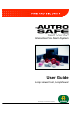
Interactive Fire Alarm System User Guide Loop viewer tool, LoopViewer Protecting life, environment and property... P-ASAFE-LV/FE, Rev.
COPYRIGHT © This publication, or parts thereof, may not be reproduced in any form, by any method, for any purpose. Autronica Fire and Security AS and its subsidaries assume no reponsibility for any errors that may appear in the publication, or for damages arising from the information in it. No information in this publication should be regarded as a warranty made by Autronica Fire and Security. The information in this publication may be updated without notice.
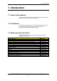
Error! Style not defined. Table of Contents 1. Introduction.....................................................................3 1.1 1.2 1.3 About the Handbook ....................................................................3 The Reader .................................................................................3 Reference Documentation............................................................3 2. General Description ........................................................4 3.
Error! Style not defined. Error! Unknown switch argument., AutroSafe Interactive Fire Alarm System, Release 3, P-ASAFE-LV/FE, Rev.
Error! Style not defined. 1. Introduction 1.1 About the Handbook This handbook is intended to provide all necessary information for the operation of the loop viewer tool, LoopViewer . 1.2 The Reader The handbook is intended to be used by Autronica Fire and Security service and technical personnel who are responsible for the installation and verification of detection loops. 1.
Error! Style not defined. 2. General Description The LoopViewer is a PC-based installation and marketing tool, running under Windows 95, 98, NT, 2000, XP. The LoopViewer includes the following main features: • Graphical TOPOLOGY view of all loop units in one loop. Presents loop with branch off (1 level), loop break position, loop short-circuit postion, and individual graphical symbols for all AutroSafe loop units.
Error! Style not defined. Error! Unknown switch argument., AutroSafe Interactive Fire Alarm System, Release 3, P-ASAFE-LV/FE, Rev.
Error! Style not defined. 3. Setting up the System 3.1 Minimum PC-requirements Intel 486 DX 100MHz or higher Windows 95, 98, NT, 2000, XP Serial COM-port (COM1 to COM4) 32Mb of RAM is recommended Monitor with resolution of 1024 x 768 HiColor (16 bit ), is recommended • Mouse or other pointing device • • • • • 3.2 Installing the Software The software consists of only one single file: LoopViewer.exe. • Copy this file to any folder/directory you want.
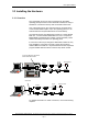
Error! Style not defined. 3.3 Installing the Hardware 3.3.1 Overview The LoopViewer can be run when connected to an AutroSafe operating panel (Fire Alarm Control Panel BS-310/320, BC-320), or standalone connected to the loop with an external interface unit. One of the serial ports on the computer must be connected to the Communication Module (BSL-310) in the operating panel or to an external interface unit (both alternatives are shown below).
Error! Style not defined. 3.3.2 Cable Connections Overview in Interface Unit WAS-2000 Consult the drawing below, and do the following: • Available with the WAS-2000 there is a ribbon cable XJA-027 with a 9-pin Dsub and a ribbon cable connector. • Connect the 9-pin Dsub connector to one of the serial ports (COM1 or COM4) on your computer and the flat ribbon connector to the BSL-310 communication module in the WAS-2000. • Connect the WAS-2000 Interface unit to the 220V AC mains outlet.
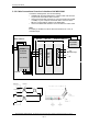
Error! Style not defined. 3.3.3 Connecting the Loop Cable to the Loop Driver Module in WAS-2000 Screw Terminal no. on Loop Driver Module BSD-310 Signal 1 OUT + 2 OUT - 3 CHASSIS 4 IN + 5 IN - 6 CHASSIS The Loop Module BSD-310 / BSD-311 must be connected to the loop you want to communicate with. Input BSD-310 + Detector 1 3 24V DC Out + 2 3 1 2 3 4 In - 2 1 Output 3 2 1 - IN 2 - OUT 3 + COMMON 4 - LED 1 5 6 Error! Unknown switch argument.
Error! Style not defined. 3.3.4 Cable Connections to an AutroSafe Operating Panel If the LoopViewer is to be connected to the Communication Module BSL-310 inside an operating panel, a flat ribbon cable XJA-027 must be used.(Available from Autronica Fire and Security AS.) A 9-pin Dsub connector for the COM-port on your computer, and a ribbon cable connector for the panel.
Error! Style not defined. 4. Operating the Tool 4.1 Overview The LoopViewer starts by asking you for the COM-port to which the XJA-027 cable has been connected. Select the COM-port and then the OK button. The LoopViewer will then check for a correct connection to a BSL-310 in a WAS-2000 or inside a panel and show this window for a few seconds: Then the LoopViewer will automatically open the Topology window as shown below.
Error! Style not defined. 4.2 The ”Topology” Window The Topology window is the window that will give you access to all functions and will show a graphical view of the AutroSafe loop. You will need to do a ‘Topology scan’ before the other functions are available. HIT Error! Unknown switch argument., AutroSafe Interactive Fire Alarm System, Release 3, P-ASAFE-LV/FE, Rev.
Error! Style not defined. 4.2.1 Select Loop Driver The Select Loop Driver button allows you to select the loop driver module (BSD-310 / BSD-311) for the loop to be looked at. By default, loop driver 1 (LD1) is selected, but the user can select any other module. Only loop drivers of the type BSD-310 or BSD-311 will be correctly handled by the LoopViewer although all modules found will be shown in the Select Loop Driver window.
Error! Style not defined. 4.2.2 The START Button Pressing the START button tells LoopViewer to find all points connected to the selected loop driver, and present them graphically in a correct electrical sequence. Points will be presented with unique symbols for each type, and with important information such as Production Number (PN), and the Loop Sequence Index (LSI). In case of illegal topologies, like multiple branch-off and loop break, these will be presented with self-explaining symbols.
Error! Style not defined. 4.2.4 The Report Button Pressing the Report button allows you to generate a report for the selected loop. The report provides useful information, as shown on the report example below. It is possible to sort by Loop Sequence Indexes (LSI) or by type. Clicking the "Make Configuration" button, allows you to generate a CSV file, which the AutroSafe Configuration Tool can import and convert to AutroConfig format.
Error! Style not defined. 4.2.5 Comfail Bargraph The Comfail status field presents the number of ALCOM communication failures per time unit. The default sample period is 5 seconds. 4.2.6 Status Bar A status bar at the bottom of the screen gives the following information: Points: LoopViewer status Gives the status of the LoopViewer at the moment, and tells if input is expected from the user. The total number of points is shown. Earth failure on + and wire (if present).
Error! Style not defined. 4.2.8 Notifications Button The LoopViewer Notification Log is a popup window where all important messages / notifications from AutroSafe components will appear. The log will contain time stamps, and the log may be copied and pasted into text editors for documentation or storing. The Notification log (separate window that describes received events) will for this version not be set in front (as the selected window) every time the LoopViewer receives an event.
Error! Style not defined. 5. List of Symbols List of all known symbols presented in topology window Loop driver (P0) Heat detector (BD-200/300/500) Optical smoke detector (BH-200/300/500) Multisensor (smoke&heat) detector (BH220/320/520) Manual callpoint (BF-200/300/500) Addressable sounder (BBR-200, BBR-110) Input / Output unit (BN-300,BN-310,BN-320,BN201) Topology ERROR Probably caused by multiple branch-off, which is illegal.
Error! Style not defined. 6. Examples of Special Topologies 6.1 Example 1: Break in Loop Wiring In this example, the LoopViewer couldn’t find the ‘IN’ side of the Loop driver, when powering up from the ‘OUT’ side. Since it can’t be known which of the points LSI-4 or LSI-3.1 is the main loop, and which is the branch, the LoopViewer presents a break symbol after both. The LoopViewer will then power up the loop from the ‘IN’ side, and find the points on the other side of the break.
Error! Style not defined. 6.2 Ex. 2: Multiple Branch-off (Star-connection) In this example, the LoopViewer has given a warning between LSI 19 and 21. This is to indicate that when closing LSI 19’s switch, more than 2 new points where powered up. The LoopViewer cannot present more than 3 points in a star-connection, and since more than 1 branch-off is illegal in an AutroSafe system, this warning is given. So in this case, LSI-21, LSI-19.1 and LSI-20.1 are connected to the same point, LSI-19.
Error! Style not defined. 6.3 Ex. 3: Inadequate Interpretation of Loop Topology In certain situations, The LoopViewer may not give a totally correct presentation of the loop topology. Several factors may affect the interpretation of the loop topology, for example, whether a point belongs to the main loop or a branch-off, which point is registered first during power up, if there is an illegal branch-off, etc.
Error! Style not defined. Normally, the LoopViewer will find out that it has made a mistake, and switch the last guess made. In this example, however, the LoopViewer meets a branch after LSI-2, and since a branch in a branch-off is illegal, it assumes that this is still on the main loop, and that the last guess (LSI-2) was correct. But as it can’t find more points on what it thinks is the main loop, it assumes the loop has a break at this point. So because of the illegal branch LSI-2.
Error! Style not defined. Error! Unknown switch argument., AutroSafe Interactive Fire Alarm System, Release 3, P-ASAFE-LV/FE, Rev.
Error! Style not defined. 7. Reader’s Comments Please help us to improve the quality of our documentation by returning your comments on this manual: Title: User Guide,Loop Viewer Tool, LV-2000 AutroSafe Interactive Fire Alarm System, Release 3 Ref. No.: P-ASAFE-LV/FE, Rev. A, 033105 Your information on any inaccuracies or omissions (with page reference): Please turn the page Error! Unknown switch argument., AutroSafe Interactive Fire Alarm System, Release 3, P-ASAFE-LV/FE, Rev.
Error! Style not defined. Suggestions for improvements Thank you! We will investigate your comments promptly.
Error! Style not defined. Error! Unknown switch argument., AutroSafe Interactive Fire Alarm System, Release 3, P-ASAFE-LV/FE, Rev.
Autronica Fire and Security AS is an international company, based in Trondheim, Norway and has a world-wide sales and service network. For more than 40 years Autronica’s monitoring systems have been saving lives and preventing catastrophes on land and at sea. Autronica Fire and Security’s most important business area is fire detection & security. Autronica Fire and Security stands for preservation of environment, life and property.