AUX One to Two Split Air Conditioner Service Manual EA、EL&HS Series Downloaded from AC-Manual.
CONTENTS Section 1 Important Notice………………………………………………………………..………1 Section 2 Technical Specifications…………………………………………………………..……2 Section 3 remote controller introductions…………………………………………………..……. 9 Section 4 Electronic Controller introductions…………………………………………….……....23 Section 5 The disassembly and the relating attention issues to the part of AUX product……......32 Part 1. Indoor unit……………………………………………………………………………..…....32 Part 2. Outdoor unit……………………………………………….………………….………..........
AUX Air Conditioner Service manual Section 1 Important Notice This service manual is intended for use by individuals possessing adequate backgrounds of electrical. Electronic and mechanical experience. Any attempt to repair the appliance may result in personal injury and property damage. The manufacturer or seller cannot be responsible for the interpretation of this information. Nor can it assume any liability in connection with its use. The information.
AUX Air Conditioner Service manual Section 2 Technical Specifications ASW-H09A+09A4/HS2R-IV Model No Indoor Unit A (System A) Items Performance Type Wall mounted model 2.5 2.5 / Dehumidify kg/h 1.0 1.0 / Heating kw 2.75 2.75 / Noise level dB(A) 40 40 62 2.3 2.3 / 2.4 2.4 / 1060 1050 2030 1070 1060 2000 4.60 4.56 8.83 4.65 4.60 8.
AUX Air Conditioner Service manual ASW-H09A+12A4/HS2R-V Model No Indoor Unit A (System A) Items Performance Type Wall mounted model 3.2 2.5 / Dehumidify kg/h 1.2 1.0 / Heating kw 3.6 2.75 / Noise level dB(A) 43 40 62 2.3 2.3 / 2.4 2.4 / 1320 970 2150 1360 1070 2300 5.74 4.22 9.35 5.91 4.
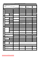
AUX Air Conditioner Service manual ASW-H12A+12A4/HS2R-VI Model No Indoor Unit A (System A) Items Performance Type Wall mounted model 3.2 3.2 / Dehumidify kg/h 1.2 1.2 / Heating kw 3.6 3.6 / Noise level dB(A) 43 43 62 2.3 2.3 / 2.4 2.4 / 1270 1270 2530 1360 1360 2500 5.52 5.52 11 5.91 5.91 10.
AUX Air Conditioner Service manual ASW-H09A+09A4/EA(L)2R1-I Model No Indoor Unit A (System A) Items Performance Type Wall mounted model 2.5 2.5 / Dehumidify kg/h 1.0 1.0 / Heating kw 2.75 2.75 / Noise level dB(A) 38 38 62 2.6 2.6 / 2.6 2.6 / 960 960 1820 950 950 1780 4.17 4.17 7.91 4.13 4.13 7.
AUX Air Conditioner Service manual ASW-H09A+12A4/EA(L)2R1-II Model No Indoor Unit A (System A) Items Performance Type Wall mounted model 3.2 2.5 / Dehumidify kg/h 1.2 1.0 / Heating kw 3.55 2.75 / Noise level dB(A) 41 38 62 2.6 2.6 / 2.6 2.6 / 1150 900 2010 1220 980 2050 5.0 3.91 8.74 5.3 4.26 8.
AUX Air Conditioner Service manual ASW-H12A+12A4/EA(L)2R1-III Model No Indoor Unit A (System A) Items Performance Type Wall mounted model 3.2 3.2 / Dehumidify kg/h 1.2 1.2 / Heating kw 3.55 3.55 / Noise level dB(A) 41 41 62 2.6 2.6 / 2.6 2.6 / 1130 1130 2230 1180 1180 2200 4.91 4.91 9.7 5.13 5.13 9.
AUX Air Conditioner Service manual ASW-12A+12A2/EA(L)2-III Model No Indoor Unit A (System A) Items Performance Type Wall mounted model 3.2 3.2 / Dehumidify kg/h 1.1 1.1 / Heating kw / / / Noise level dB(A) 41 41 62 2.56 2.56 / 2.56 2.56 / 1250 1250 2500 / / / 5.7 5.7 11.4 / / / Cooling EER Heating Electrical Data Refrigerating System W/W φ-V-Hz Cooling Rated input Heating Cooling Rated current Heating W A 1 / 208-230V~/ 60Hz Length m 2 2 4.
AUX Air Conditioner Service manual Section 3 Remote Controller Introductions Part 1. Model eg: ASW-H09A+09A4/HS2R-IV ASW-H12A+12A4/HS2R-VI ASW-H09A+12A4/HS2R-V ASW-12A+12A2/EA(L)2-III a. Names and functions of the button YK(R)-C/01E YK(R)-C/02JE Following function description is according to model of YK(R)-C/01E.The number in the bracket is to the model of YK(R)-C/02JE accordingly ① Sleeping button (⑧) Used to set or cancel (press it again) sleep mode operation.
AUX Air Conditioner Service manual ⑤ Temp increasing button (⑤) Press the button once , the setting temperature increases 1℃ . Press the button continuously for more than 1 second . the setting temperature increases at the speed of 4℃/s . the highest setting temperature is 32℃ . ⑥ Select button for operation mode (⑥) Which enables you to select different operation modes . after each pressing , the operation mode will be changed . It shows in the following display .
AUX Air Conditioner Service manual b. Display YK(R)-C/01E YK(R)-C/02JE Following function description is according to model of YK(R)-C/01E.The number in the bracket is to the model of YK(R)-C/02JE accordingly ① Emission display When the remote controller sends correct and effective signal each time, the sign will glitter once. ② Fan speed display Press the Fan speed selection button ,the fan speed will display.
AUX Air Conditioner Service manual Press the HEALTH button , can choose anions to emit or stop . ⑥ Sleep display This indicate whether the air conditioner is in sleep mode or not. Remarks : it is readable to list all of items in the picture , when the mode operates , only most of items c. Application method Model: YK(R)-C/01E ★ Fix batteries 1. Slide open the cover according the direction indicated by arrowhead. 2. Put into two brand new batteries (7#).
AUX Air Conditioner Service manual 4. Press the “ ” button. the operation indicator is on. the air-conditioner starts to operate the Cooling or Heating mode. Press the button again. the air-conditioner stops. ★ Circulation operation mode 1. Press the MODE button. select the Circulation operation mode. 2. Press the “ ” button. you can select fan speed. The type of H、M series: You can select fan speed from “High”. “Low”. “Mute”. The type of E series: You can select fan speed from “High”. “Mid”. “Low”. 3.
AUX Air Conditioner Service manual 1. Press the TIMER button. select the “Timer OFF”. the remote controller display “ displays intermittently. 2. Adjust time through pressing the or ” ; “ OFF ” button. 3. Press the SET button then. the setting is finished. Remark: The remote controller can be set 24 hours. ★ Sleeping operation mode 1. Press the “ ” button. the sleeping indicator light of indoor unit flashes on. 2. After the setting of sleeping mode.
AUX Air Conditioner Service manual from 16-32℃. 3. Press the “ ” button. you can select fan speed. The type of H、M series: You can select fan speed from “Power”. “High”. “Low”. “Mute”. The type of E series: You can select fan speed from “Auto”. “High”. “Mid”. “Low”. 4. Press the “ ” button. the operation indicator is on. the air-conditioner starts to operate the Cooling or Heating mode. Press the button again. the air-conditioner stops. ★ Circulation operation mode 1. Press the MODE button.
AUX Air Conditioner Service manual 1. Press the TIMER button. select the “Timer ON”. the remote controller display “ displays intermittently. 2. Adjust time through pressing the or button. 3. Press the TIMER button once again. the “ Timer ON ” setting is finished. ☆ Set the “ Timer OFF ” ( It is effective only when the air conditioner is running ). 1. Press the TIMER button. select the “Timer OFF”. the remote controller display “ displays intermittently. 2.
AUX Air Conditioner Service manual Part 2. Model eg : ASW-H09A+09A4/EA(L)2R1-I ASW-H12A+12A4/EA(L)2R1-III ASW-H09A+12A4/EA(L)2R1-II a. Names and functions of the button The closing state of remote controller: ① “+” button This button can set room temperature. Press it once ,the temperature increases 1 ℃ .Press it continuously, the temperature increases at the speed of 4℃/s. This function is invalid when the appliance at the Fan and Auto mode.
AUX Air Conditioner Service manual The opening state of remote controller: ① “+” button This button not only can adjust clock time and the timer time but also can set room humidity. Adjusting clock time and timer time Press it once ,the time increases one minute. Press it for 1 to 3 seconds, time display will increase at the speed of 2min/s. For 3 to 5 seconds, it will increase at the speed of 10min/s. For more than 5 seconds, it will increase at the speed of 10min/s.
AUX Air Conditioner Service manual Press the button once again. The symbol disappears. the function is cancelled at the same time. ⑥“TIMER/CLOCK” button Setting the “ON/OFF” timer time When remote controller is at the on/off state. Press this button .the LCD flickers the symbol. Press the “+”or “-”button to set the timer time. After finishing it. press this button again in 10 seconds to affirm. If the setting time is the same as the current time. this setting is invalid.
AUX Air Conditioner Service manual b. Application method ★ Fix batteries 1. Slide open the cover according the direction indicated by arrowhead. 2. Put into two brand new batteries (7#). position the batteries to right electric poles (+&-). 3. Put back the cover. Make sure to connect the wire to independent power source socket before you use the remote controller. Note: the waste battery shall be disposed properly. ★ Cooling / Heating operation mode (Cold wind type has no heating function) 1.
AUX Air Conditioner Service manual Press the button again. the air-conditioner stops. Remark: In the circulation operation mode. to set the temperature is noneffective. ★ Automatic operation mode 1. Press the MODE button. select the automatic operation mode. 2. Press the “ FAN ” button. you can select fan speed. The type of H、M series: You can select fan speed from “Power”. “High”. “Low”. “Mute”. The type of E series: You can select fan speed from “Auto”. “High”. “Mid”. “Low”. 3. Press the “ ” button.
AUX Air Conditioner Service manual c. Attention ★ ★ ★ ★ ★ ★ ★ ★ ★ ★ The remote controller transmits signals to the system. Aim the remote controller towards the receiver on the air-conditioner. The remote controller should be within 8 meters away from the receiver. No obstacles between the remote controller and receiver. Don’t drop or throw the remote controller. Don’t put the remote controller under the forceful sunrays or heating facilities and other heating sources. Use two 7# batteries.
AUX Air Conditioner Service manual Section 4 Electronic Controller introductions 1. Automatic operation mode 1.1 When air conditioner is running.it will automatically detect indoor temperature by comparison to standard temperature There with to select operation mode:Refrigeration. Heating or dehumidify. (default will be set as 24 ℃) 1.2 When indoor temperature≥27℃.running mode will be cooling. 1.3 When indoor temperature is between 20℃ and ℃. Dehumidify mode will function(always mute). 1.
AUX Air Conditioner Service manual 4. Ventilation control function 4.1. At ventilation mode.outdoor unit is always closed. 4.2. indoor fan functions according to set air input.without high power wind. 4.3. vertical air blade operates according to operating requirement of remote control. 4.4. without sleep function.have got timing function. 5. Heating Function 5.1. In heating mode.temperature range is setted between 16℃ and 32℃. 5.2. While in heating function.
AUX Air Conditioner Service manual Prevent cold wind function when compressor out of working: 1) When T e presents falling state. When T e>25℃.the indoor fan motor will be in feeble wind model. T e≤25℃ .the indoor fan motor will trun off. 2) When T e presents rising state. and T e≥28℃.the indoor fan motor will be in feeble wind model.T e <28℃.the indoor fan motor will trun off. Residual heat function: When the T inter- panel>35℃.indoor fan motor will run in feeble wind model.and when the T interpanel≤35℃.
AUX Air Conditioner Service manual compressor starts to work with defrosting mode. When defrosting is finished.the compressor stops running. After 20 minutes. the four-way valve starts operating. After another 20 seconds.until all compressors exit defrosting and get into heating mode. Indoor fan works as cold air protection function. Indoor fan works as cold air protection function. 5.7.3 Condition of ending defrosting operating: T outer panel ≥12℃ or defrosting time≥ 12min.
AUX Air Conditioner Service manual Time of turning off can only be set when the machine is on. It cann’t be set when the machine is off. When it comes to the set time. both inside and outside unites stops operation. 7.3 Set time operation Time of turning on can only be set when the machine is off. It cann’t be set when the machine is on. When it comes to the set time.Both of the inside and outside unites starts operation. 8. Emergency switch Turn the machine on by pressing the on/off button.
AUX Air Conditioner Service manual delay 30S to open indoor fan. with a mute wind speed. at the same time malfunctions shown. 9.4.3 When the deviation of T c signal of outdoor coil temperature sensor is detected. strobolamp flickers. and malfunction is indicated. If the remote manipulator signal of heating is received. press heating for 50min.defrosting for 10min.to cycle heating. The rest mode function as usual. 9.5 Indoor PG .motor fault handling After the indoor motor is put on voltage.
AUX Air Conditioner Service manual Chart 3 shows the step motor swinging angle of E series conditioners of 9000Btu and12000Btu. the angle between fully open position and complete shutdown hereafter is called omnirange angle. The omnirange angle of E mold is 150°. In the operational process of repeating motor. the operational angle is always memorized. repeating motor follows 4 phase 8 beating type of drive. 1. Reset action of first electrify. step motor opens an omnirange angle to its opening direction.
AUX Air Conditioner Service manual 1. position of complete shutdown 3. refrigerating pendulum terminal point 5 heating position 2. refrigeration position 4 heating pendulum terminal point 6 position of complete shutdown Swinging angle of repeating motor for H series off-set air conditioner 9000Btu and 12000Btu 1. When power is on. the air blade makes a complete shutdown. with a swing rate of 22°/ s 2. When machine is on. the air blade makes a complete shutdown. then swing to its initial point.
AUX Air Conditioner Service manual 1. position of complete shutdown 3. refrigerating pendulum terminal point 5 heating position 2. refrigeration position 4 heating pendulum terminal point 6 position of complete shutdown Attached is the electrical resistance for wind speed. Cooling Cooling High R7 Strong R12 Soft wind R9 & power wind heating R9 12K 510 1230 1.2K 1200 1.2K 1100 15K 1.2K 1180 3K 1150 3K 1050 20K 2K 1130 5.1K 1100 5.1K 1000 27K 2.7K 1080 8.2K 1050 8.2K 950 36K 3.
AUX Air Conditioner Service manual Section 5 The disassembly and the relating attention issues to the part of AUX product Attention: Turn off the air-conditioner and pull out the plug of the power supply before the service. Part 1 Indoor unit: No. Part Operation Process Panel 1) Turn off the air-conditioner and cut off 1 the power supply; 2) Tear the adhesive tape sticking to the panel.
AUX Air Conditioner Service manual No. 2 Part Operation Process Electrical 1) Do No. “1” firstly; component 2) Pull out all tie-in connecting with PCB and the temperature sensor. etc.; 3) Screw off the screws and bolts as indicated in the picture. Untie the outdoor unit’s interconnection cord and power supply cord from the terminal of the electrical box. 4) If the main PCB board is loosed by chance. remove it away; 3 Water draining tank 4 Evaporator 1) Do No.”1” . “2” and “3” firstly; 1) Do No.
AUX Air Conditioner Service manual Part 2. Outdoor unit: This chart shows the the dismantlement process of outdoor unit of heat pump model..The only cooling model can refer to this flow: figure1 figure2 1. Loosen the two bolts on the electrical cover (as shown in chart 1) Take down the electrical cover unit. 2. Loosen the two bolts on the 3 fixed wire calmp. loosen the bolt on fixed powerline and communication lines of inside and outside unit.
AUX Air Conditioner Service manual figure4 figure5 figure6 4. Loosen the bolt of fixed Top cover board. as shown in figure 4. take down Top cover board 5. Loosen the bolt of fixed small board. as shown in figure 5. take down the small board. 6. According to the above approach. dismantle the bolts of fixed right side board. large board. Left Side board and air intake fencing components. and take down these parts by turns. as shown in figure figure7 figure8 figure9 7. As shown in chart 7.
AUX Air Conditioner Service manual component. 14. As in figure 10.dismantle the four bolts on the fixed partition plate. and take down partition plate 15. Unsolder the 4 welding points shown in chart 11. 16. As shown in chart 12. dismantle condenser assembly. A. B system compressor and valve plate component. figure10 figure11 figure12 figure13 figure14 17. When reconnecting the connecting pipes of inside and outside unit. please strictly follow chart 14. A system match with A indoor unit.
AUX Air Conditioner Service manual Section 6 Trouble Shooting Guide 1. Starting Items to check 1.1 Make sure input voltage must be within the±10% range of the nominal voltage. If the operation electric tension exceeds scope.the air conditioner may not working normally. 1.1 Make sure the indoor/outdoor communication connecting wire is correct. This series of unit model have two indoor unit.with a communication cable connected to the outdoor unit.
AUX Air Conditioner Service manual 2. No power supply(out of work completely)-tentative diagnosis 2.1. Check item 1) Does the input voltage is correct? 2) Does AC power wires connected correctly? 3) Does the output voltage of voltage stabilizer l7805 (ic2) is correct? 4) Does between indoor and outdoor unit communication is normal? 2.2. Fault diagnosis procedure Note:There is according with an outdoor unit and two indoor unit.and a set of PCB. Please check them accordingly.
AUX Air Conditioner Service manual 8 Air-conditioner starts working after pressing ON/OFF on the remote 10 Normal 11 Check outdoor power connection and compressor 12 Check the AC voltage of PCB board. 13 Signal direction shown on the remote controller.
AUX Air Conditioner Service manual 3.2. fault diagnosis procedure 1 Unplug the indoors and outdoors and re-plug after about 5 seconds 2 Judge the LED light is on or not? Does Digital tube shows E4 error code or not? 3 Reference to the previous page about error diagnosis steps 4 Check chip output on the controller is normal or not? 5 Micro-controlled chip error 6 Check the input voltage of the fan motor enough or not 7 PCB error 8 Replace PCB 9 Probe position 10 PCB Cn10 11 Status 12 Normal voltage 13 #2.
AUX Air Conditioner Service manual 4、Malfunction of the outer door motor 4.1. Check item 1) Is input voltage normal? 2) Is the connecting way of exterior connecting terminal correct? 3) Is indoor and outdoor communication normal? 4.2. Fault diagnosis procedure Note:Each air conditioner is correspondent with an outdoor unit and two indoor unit.and a set of controller. Please check accordingly. Outdoor unit has two independent sets of systems. with a common fan.
AUX Air Conditioner Service manual 1 Unplug the power and re-plug after about 5 seconds 2 Turn on air-conditioner with remote controller. 3 LED and digital tube in the indicator board on or not? 4 Confirm “ powerless” error diagnosis steps normal 5 Air blade moves when press “ air flow” ON 6 Normal 7 Voltage changes between the #35.#36.#37.
AUX Air Conditioner Service manual 1. Re-start in five minutes after all of above problems improved 2. Normal 3. Is the voltage of outdoor chip IC1#42 DC5. 0V? 4. Chip IC1 abnormal 5. Voltage of #15.#16 of outdoor chip IC1 high or not? 6. Chip IC1 abnormal 7. Voltage of the connection points between IC2 #15. #16 and 4-way valve relay (RE3. RE4) low or not? 8. IC 2 abnormal 9. Relay out-put normal or not? 10. Replace IC4 11. Replace relay ( RE3. RE4) 12.
AUX Air Conditioner Service manual 7. Replace battery 8. Remote LCD display normal 9. LCD display error 10. Press the remote “ON/OFF” button. transmitting signal shows 11. Replace the button 12. Voltage of remote chip IC1 changes 13. Chip error 14. Voltage of Q1 changes 15. Replace three-electro tube 16. Voltage of Led changes 17. Transmitting error 18. Receiver error 8. PCB Checking 8.1. Pay attention to replacing the parts: 1) Human body takes static electricity.So before repairing and replacing parts.
AUX Air Conditioner Service manual 1 Check the error part 2 Unfix the error part 3 Replace the part 4 Check the performance of new part 5 Service done 8.3. Detail Process No. Malfunction Cut off the power and check the fuse on 1 the PCB Checkpoint Fault or not? Cause 1.Over voltage 2.Short circuit of indoor fan motor Check Voltage ● Rectifier circuit goes wrong 1.Whether have got normal AC voltage ● Step-down voltage transformer broken on CN9 or not? 2.
AUX Air Conditioner Service manual 9. Fault analysis of major parts 46 Downloaded from AC-Manual.
AUX Air Conditioner Service manual Section 7 Explosion View 1. Indoor Unit: Model eg: ASW-H09A4/HS2R-IVA ASW-H12A4/HS2R-VA ASW-H12A4/HS2R-VIA ASW-H09A4/HS2R-IVB ASW-H09A4/HS2R-VB ASW-H12A4/HS2R-VIB 47 Downloaded from AC-Manual.
AUX Air Conditioner Service manual Parts List No.
AUX Air Conditioner Service manual Model eg: ASW-H09A4/EA(L)2R1-IA ASW-H09A4/ EA(L)2R1-IB ASW-H09A4/ EA(L)2R1-IIB、 ASW-H12A4/ EA(L)2R1-IIIB、 ASW-12A2/EA(L)2-IIIB ASW-H12A4/EA(L)2R1-IIA ASW-H12A4/EA(L)2R1-IIIA ASW-12A2/EA(L)2-IIIA 49 Downloaded from AC-Manual.
AUX Air Conditioner Service manual Parts List No.
AUX Air Conditioner Service manual 2. Outdoor Unit: Model eg: AS-H09A+09A4/HS2R-IV AS-H12A+12A4/HS2R-VI AS-H09A+12A4/EA(L)2R1-II AS-12A+12A2/EA(L)2-III AS-H09A+12A4/HS2R-V AS-H09A+09A4/EA(L)2R1-I AS-H12A+12A4/EA(L)2R1-III 51 Downloaded from AC-Manual.
AUX Air Conditioner Service manual Parts List No 1 2 3 4 5 6 7 8 9 10 11 12 13 14 15 16 17 18 19 20 21 22 23 24 25 26 27 28 29 30 31 32 33 34 35 36 37 38 39 40 41 Name Condenser Top cover board Capillary assembly for system B Capillary assembly for system A Compressor connecting line for system A Compressor connecting line for system B Grille assembly Rubber supporter Right-hand board Partition plate Electrical box cover board Compressor discharge tube for system A Compressor air return tube for system A
AUX Air Conditioner Service manual 42 43 44 45 46 47 48 49 50 Fan motor Cushion Fan Six-angle nut Steel grille Big panel Handle Left-hand holder plate Small panel 1 1 1 1 1 1 1 1 1 53 Downloaded from AC-Manual.
AUX Air Conditioner Service manual Section 8 Cooling Cycle Diagram The following chart shows the schematic circuit of the heat pump model.
AUX Air Conditioner Service manual Section 9 Wiring Diagram Applicable to HS \E 1. Indoor Unit Auto Button Multi-Heat Indoor Unit Electric Chart 2. Outdor Unit a. Heat Pump Model B Controlling Panel A A B Overcurrent Protector Overcurrent Protector Multi-Heat Two Split System A B 55 Downloaded from AC-Manual.
AUX Air Conditioner Service manual b. Single Cooling Model 56 Downloaded from AC-Manual.
3. Wiring diagram for Original Multi type a. Indoor unit Wiring diagram b. Outdoor unit Wiring diagram 57 Downloaded from AC-Manual.
AUX Air Conditioner Service manual Section 10 Date Page Service Record Part Cause 57 Downloaded from AC-Manual.