
Service manual

AUX Air Conditioner Service manual
35
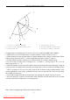
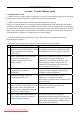
figure4 figure5 figure6
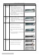
4. Loosen the bolt of fixed Top cover board. as shown in figure 4. take down Top cover board
5. Loosen the bolt of fixed small board. as shown in figure 5. take down the small board.
6. According to the above approach. dismantle the bolts of fixed right side board. large board. Left
Side board and air intake fencing components. and take down these parts by turns. as shown in figure
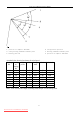
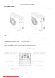
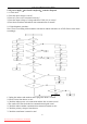
figure7 figure8 figure9
7. As shown in chart 7. dismantle the fixing nut of the axial flow fan blade(right-handed nut). take
down axial flow fan
8. Dismantle the bolts of fixed motor and motor holder. takes down the motor and motor holder. as
shown in chart 8.
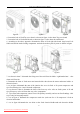
9. As in figure 9.dismantle the nuts of the junction box cover in fixed A. B system compressor. and
tip-off connecting wire 1 and 2 from the compressor.
10. As shown in chart 9. dismantle the bolts of the four-way valve coils on fixed system A. B. and
tip-off four-way valve coil from four-way valve components.
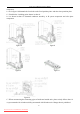
11. Tip-off the tube temperature sensor from A B capillary assembly. and cut out fixed bandage(this
step is only for heat pump model.)
12. As in figure 9. dismantle the compressor earth wire (each one for A. B compressor)fixed on
electrical unit holder.
13. As in figure 9.dismantle the two bolts on the fixed electrical holder.and take down the holder
Downloaded from AC-Manual.com Manuals