
User Manual


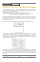

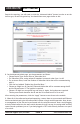
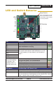


Table Of Contents

AW2400mTR User’s Manual
PAGE 10
Technical support (650) 384-0000 www.avalanwireless.com
“Easy Key” Conguration
In most cases, the browser interface is a better choice for conguring the modules.
But they also can be congured as a point-to-point bridge or a point-to-multipoint
group using the DIP switches. When this method is used, the module that will oper-
ate as the access point provides a unique network ID calculated from its MAC ad-
dress and a unique random encryption key programmed into it during manufacture.
If you do congure a set of modules this way, be aware that they will all have the
factory default IP address of 192.168.1.17. If you later need access to a module via
the browser interface, use the IP Finder utility, select the individual unit and give
it a unique IP address.
Initial Setup:
1. Select the module that will operate as the access point (AP) and set its DIP
switch 1 on (down). Set DIP switch 1 o (up) on the module(s) that will oper-
ate as subscriber units (SUs).
2. Select matching frequency channels on all modules or select automatic chan-
nel selection by leaving DIP switches 3-8 o.
3. Power up the AP module. Its link quality LEDs will begin blinking sequentially,
showing that the module is hunting for an SU to exchange keys with.
4. Power up an SU module (its DIP switch 1 is o). This module’s link quality
LEDs will also begin blinking sequentially showing that it is hunting for an AP
to supply a network key.
5. Connect an Ethernet cable from the AP module to the SU module and the two
modules will automatically exchange keys. (Do not connect through a switch
or hub, but cable directly with a regular patch or crossover cable.)
• On the AP module, the link quality LEDs will still blink sequentially in key
exchange mode and the TX LED will light showing successful key exchange
• On the SU module, the link quality LEDs will no longer blink sequentially,
but one of the green link quality LEDs will slowly blink to indicate success-
ful key exchange.
6. Repeat steps 4 and 5 for any other SU modules to be congured to the same
A P.
7. disconnect the Ethernet cable and cycle power on all modules for the new
keys to take eect. LED behavior should reect normal RF operation once the
units are deployed.