
User's Manual


PAGE 7
Technical support (650) 384-0000 www.avalanwireless.com
MOD090-HP
User’s Manual
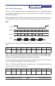
SPI0 - LEDs and DIP Switches
SPI0 is a master mode SPI that sends out 4 bytes per transaction. The rst two bytes
are alignment bytes and the last two contain the LED data on MOSI0, and the DIP
switch data on MISO0.
The rst alignment byte is 0x55, and the second is 0xAA. These two bytes are used
to determine the start of the transaction (0x55) and the start of the data (0xAA).
LEDs:
/CS_LED
MISO0 XX XX Byte3 Byte4
MOSI0 0x55 0xAA Byte3 Byte4
SCK0
A bit that is set in either of these bytes indicates that the corresponding LED should
be on.
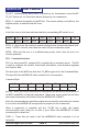
Byte3 b7 b6 b5 b4 b3 b2 b1 b0
PWR RX_
ACT
LCH5 LCH4 LCH3 LCH2 LCH1 LCH0
PWR: Turns on when the rmware is running. In troubleshoot mode PWR changes
states on the AP every time a search for more SUs takes place. On a SU PWR chang-
es state every time the SU responds to a search for more SUs.
RX_ACT: Indicates when data trafc has been received by the RF. RX_ACT will be
set for 32ms when data has been successfully received.
LCH5..0: Indicates what RF channel is currently in use. In troubleshoot mode these
bits indicate what the unit’s device ID is.
Byte4 b7 b6 b5 b4 b3 b2 b1 b0
TX_
ACT
- RFQ5 RFQ4 RFQ3 RFQ2 RFQ1 RFQ0