AW900iTR USER’S MANUAL 900 MHz Indoor Wireless Ethernet Radio Industrial-grade, long-range wireless Ethernet systems AvaLAN W I R E L E S S
AW900iTR User’s Manual Thank you for your purchase of the AW900iTR Indoor Wireless Ethernet Radio. The AW900iTR includes: (1) AW900iTR radio in extruded aluminum box (1) AW2-900 2.5dBi omnidirectional antenna (1) 110 VAC to 12 VDC power adapter The AW900iTR-PAIR includes: (2) AW900iTR preconfigured radios in extruded aluminum box (2) AW2-900 2.5dBi omnidirectional antenna (2) 110 VAC to 12 VDC power adapter TABLE OF CONTENTS Quick Start Guide . . . . . . . . . . . . . . . . . . . .
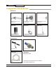
AW900iTR User’s Manual Compatible Accessories Antennas AW11-900 AW10-900 AW15-900 900 MHz Directional 11 dBI YAGI Antenna 900 MHz Directional 10 dBI Panel Antenna 900 MHz Directional 15 dBI YAGI Antenna AW3X-900 900 MHz Omnidirectional 3 dBI Armored Antenna AW5M-900 900 MHz Omnidirectional 5 dBI Magnetic Antenna AW5P-900 900 MHz Omnidirectional 15 dBI Pole Antenna Accessories AW-12VA AW-LA Auto Adapter Lightning Arrestor AW-RFx900 x = 4ft, 10ft, 25ft or 50ft 900 MHz Antenna Extension Cab
AW900iTR User’s Manual Quick Start Guide PROGRAMMING: Step 1. Gather the AvaLAN radios, power supplies, 2x CAT5 cables and a computer with an RJ45 Ethernet interface. Step 2. Connect the radios one at a time directly to the PC via an Ethernet cable. Set your computer to an IP address of 192.168.17.1 (refer to page 6 for detailed instructions). Enter the radio’s default IP address* of 192.168.17.17 into a web browser. Step 3. Enter the password and click login. The default password is “password”. Step 4.
AW900iTR User’s Manual Operational Summary The AW900iTR Radio allows the user to create a long-range, wireless Ethernet network with up to 16 subscriber units per access point. The configuration may include any combination of AW900iTR, AW900xTR and AW900xTP radios. (Please note that older AvaLAN 900 MHz radios can exist on the same LAN but cannot be used to form wireless links with the AW900iTR units because link encryption protocols have changed.
AW900iTR User’s Manual Digital Setup 1. Digital configuration is done by means of the AW900iTR’s built in browser interface. It should be powered on and connected at least temporarily to a network containing a computer that can run a conventional web browser. 2. Download the AvaLAN IP Discovery Utility from our website and extract ipfinder.exe from the zip archive, placing it on your desktop or in a convenient folder. http://www.avalanwireless.com/marketing_resources/downloads/ipfinder.
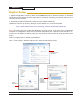
AW900iTR User’s Manual Click “Use the following IP address” Populate the following information: IP address: 192.168.17.17 Subnet mask: 255.0.0.0 Default gateway: leave blank Click OK Click OK Click Close 3. Run the IP Discovery Utility, ipfinder.exe and you should see a window similar to the view on the next page. The AW900iTR should appear in the list at the default IP address of 192.168.17.17. If it does not, click “Search” to regenerate the list.
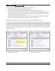
AW900iTR User’s Manual 4. Double click the list item that refers to the AW900iTR being configured. You should see a second window that is similar to this: Your computer’s current IPV4 Ethernet address Current IP of AvaLAN Radio The information on the left is the current status of the radio, while the boxes on the right allow you to change it. It is important that the IP address of the AW900iTR is in the same subnet as your computer. For example, if the subnet mask is 255.255.255.
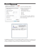
AW900iTR User’s Manual 7. The admin page has sections similar to the login page showing radio statistics and device information plus it adds several new sections. The Device Settings section allows setting the network information and choosing an RF frequency channel. The default is to allow the radio to choose its own frequency based on minimizing interference. If you set a fixed channel, make sure the AP and all SUs use the same one.
AW900iTR User’s Manual 8. On the Advanced Admin page, set the parameters as follows: • Choose Device Type: Access Point or Subscriber Unit. • For Subscriber Units, assign unique ID numbers in numeric order from 1 to 16. • For an Access Point, enter the number of Subscriber Units that will be communicating with it. • Choose an 8-digit hex (0-9 and A-F) Network Name that will be common among the AP and its SUs and enter it. The hyphen is required. • Choose a 32-digit hex encryption key and enter it.
AW900iTR User’s Manual LCD Display During boot up: After boot up LCD will display: 1. Current Version Link Quality Up arrow (Transmit (TX)) Down arrow (Received (RX)) 2. Serial Number Device type: AP or SU Channel: CH (current channel) 3. IP Address* NOTE: *When configured for DHCP mode, the display will look like the image above at boot up. If it fails to recieve an IP address within 20 seconds, it will default back to the IP address used prior to reboot. The factory default IP address is 192.168.
AW900iTR User’s Manual 900 MHz Channels Channel 0 1 2 3 4 5 6 7 8 9 10 11 12 Center Frequency Auto Mode 903.12500 MHz 905.20833 MHz 907.29167 MHz 909.37500 MHz 911.45833 MHz 913.54167 MHz 915.62500 MHz 917.70833 MHz 919.79167 MHz 921.87500 MHz 923.95833 MHz 926.04167 MHz Limited Warranty This product is warranted to the original purchaser for normal use for a period of 360 days from the date of purchase.
AW900iTR User’s Manual Technical Specifications PARAMETER SPECIFICATIONW RF transmission rate 1.536 Mbps Ethernet throughput 935 Kbps Output power +21 dBm (4 Watts EIRP when used with 15 dBi antenna) Receiver Sensitivity -97 dBm at 10-4 BER Range 40 miles line-of-sight with 15 dBi antenna RF channels 12 non-overlapping channels with 2.
AW900iTR User’s Manual Radio Status Information The Login or Admin pages of the radio’s built-in web browser interface provide many useful pieces of information that let you know how well the wireless link is working: Top of Web Page Version MAC Address Ethernet Uptime Current version of the radio’s Ethernet interface. Radio’s hardware MAC Address. Status of Ethernet connection: 10 Mbps or 100 Mbps, full or half duplex, connected or disconnected.
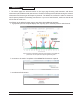
AW900iTR User’s Manual Antenna Alignment Guide Please be sure to consider the following when installing antennae from AvaLAN: Vertical polarization Omni-antenna Figure 1 11 dBi antenna Horizontal polarization Figure 2 Do not aim the omni-antennae directly at each other Technical Support (650) 384-0000 PAGE 15 www.avalanwireless.
AW900iTR User’s Manual ATTENTION: When multiple 900 MHz antennas are installed in one area and face the same direction, antennas should be spaced a minimum of 12 feet apart. When multiple antennas are installed in one area and face different directions, antennas should be spaced a minimum of 5 feet apart. Horizontal polarization 0-deg. separation 45-deg. separation 5 ft physical separation 12 ft physical separation Vertical polarization Technical Support (650) 384-0000 PAGE 16 www.avalanwireless.
AW900iTR User’s Manual Transmitter to Reciever Placement If radios are installed either indoors or outdoors at distances closer than recommended, antennas can overpower each other and cause undesired effects. If testing radios within one or two feet, remove both antennas. The radios will still be able to signal each other at close distances. This applies to both indoor and outdoor units.