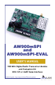
AW900mSPI and AW900mSPI-EVAL USER’S MANUAL 900 MHz Digital Radio Transceiver Module and Evaluation Kit With SPI or UART Data Interface Industrial-grade, long-range wireless Ethernet systems AvaLAN W I R E L E S S
AW900mSPI User’s Manual Thank you for your purchase of the AW900mSPI 900 MHz Digital Radio Transceiver Module with SPI or UART Data Interface. The Module itself may be ordered in quantities of ten as the AW900mSPI-10.
User’s Manual AW900mSPI Table of Contents Features and Specifications . . . . . . . . . . . . . . . . . 4 Technical Summary . . . . . . . . . . . . . . . . . . . . . . . 5 Module Physical Interface . . . . . . . . . . . . . . . . . . 6 Module SPI Interfaces . . . . . . . . . . . . . . . . . . . . . 6 Module UART Interface . . . . . . . . . . . . . . . . . . . . . 10 Module Command Set . . . . . . . . . . . . . . . . . . . . . 12 Programming Examples . . . . . . . . . . . . . . . . . . . .
AW900mSPI User’s Manual Features and Specifications • 1.54 Mbps DSSS Radio with High Speed SPI and UART Data Interfaces • FCC/IC Certified modular approval • 128 Bit AES Encryption – FIPS 197 NIST Certified • 148 dB link budget at 900 Mhz enables exceptional range • 4 Watts EIRP with 15 dBi antennae (+21 dB conducted) • -112 dB receiver sensitivity with 15 dBi antennae (-98dB at port) • TDMA MAC supports up to 63 concurrent subscribers • Low power consumption: 0.75 Watts in transmit, 0.
User’s Manual AW900mSPI Technical Summary The AW900mSPI modules from AvaLAN Wireless have an on-board Baseband processor, the XC1220 from AvaLAN Wireless. The XC1220 handles all RF timing, data buffering, AES encryption, RF data transfers and statistics gathering. The XC1220 must be connected to a host microcontroller via a Serial Peripheral Interface (SPI) or a Universal Asynchronous Receiver/Transmitter (UART).
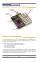
AW900mSPI User’s Manual Module Physical Interface RF Antenna RPSMA RF Section AvaLAN XC1220 Chip Pin 1 Pin 17 Module SPI Interfaces Serial Peripheral Interface (SPI) is a full duplex synchronus serial interface that allows data to be shifted in and out of the AvaLAN Baseband Processor (XC1220) 8 bits at a time, most significant bit first.
User’s Manual AW900mSPI Here are the Signal definitions for the AW900SPI in SPI mode: Pin Number Name Description 1 Vcc 3.3 vdc for XC1220 2 /CS_LED Chip select for LEDs and DIP switches (active low)C 3 /CS_PD Chip select for external programming devicehip s 4 SCK0 Serial clock for LEDs and DIP switches 5 MISO0 Data in for LEDs and DIP switches 6 MOSI0 Data out for LEDs and DIP switches 7 GND XC1220 Ground 8 Error Flag 1=last command not understood.
AW900mSPI User’s Manual SPI0 - LEDs and DIP Switches SPI0 is a master mode SPI that sends out 4 bytes per transaction. The first two bytes are alignment bytes and the last two contain the LED data on MOSI0, and the DIP switch data on MISO0. The first alignment byte is 0x55, and the second is 0xAA. These two bytes are used to determine the start of the transaction (0x55) and the start of the data (0xAA).
User’s Manual AW900mSPI TX_ACT will be set for 32ms when data is queued up for transmission. RFQ5..0: Indicates the quality of the RF link. The lowest quality is only b0 set, the highest quality is reached when b5 is set. DIPs: A bit that is set in this byte indicates that the corresponding DIP switch is on. Byte3 b7 b6 b5 b4 b3 b2 b1 b0 DCH5 DCH4 DCH3 DCH2 DCH1 DCH0 MODE - DCH5..0: Used to set the radio into manual channel mode and use the channel indicated. If DCH5..
AW900mSPI User’s Manual Module UART Interface Here are the Signal definitions for the AW900SPI in UART mode: Pin Number Name Description 1 Vcc 3.
User’s Manual AW900mSPI specified to be at least two intervals. Also, sometimes a Parity Bit is sent between D7 and the Stop Bit, but this is rarely done anymore. UART Mode LEDs and DIPs: With the UART firmware running, the LED definitions are the same as for SPI mode and provide diagnostic information if desired.
AW900mSPI User’s Manual Module Command Set The Command Sets for SPI and UART modes are somewhat different: SPI Command Set Command Byte - HEX Command 0x01 getStatus 0x02 getNetworkKey 0x03 getPrivateKey 0x04 getDeviceID 0x05 getStats 0x06 getVersion 0x07 not valid 0x08 getNumberofConnectedSUs 0x09 getRSSIreadings 0x0A getDATAPacket 0x81 setStatus 0x82 setPublicKey 0x83 setPrivateKey 0x84 setDeviceID 0x85 setReset 0x86 not valid 0x87 not valid 0x88 not valid 0x89 not
User’s Manual AW900mSPI UART Command Set Command Byte - HEX Command 0x00 getStatus 0x01 getNetworkKey 0x02 getPrivateKey 0x03 getDeviceID 0x04 getStats 0x05 getVersion 0x06 getConfig 0x07 getNumberofConnectedSUs 0x08 getRSSIreadings 0x09 not valid 0x80 setStatus 0x81 setPublicKey 0x82 setPrivateKey 0x83 setDeviceID 0x84 setReset 0x85 not valid 0x86 not valid 0x87 not valid 0x89 not valid 0x8B setDATAPacket In the Command Descriptions that follow, the command codes
AW900mSPI User’s Manual Status Command The getStatus command is used to find out the current status of the module. getStatus Byte 1 SPI Mode: UART Mode: 0x01 0x00 b7 b6 b5 b4 b3 b2 b1 b0 RFState Radio - - CH3 CH2 CH1 CH0 RFState: When set this bit indicates that the RF is currently connected. Radio: Indicates what mode the radio is in, when set it is in active mode. When clear the RF is in standby mode. CH3..0: Indicates what channel the RF is currently using.
User’s Manual AW900mSPI Network Key Command The Network Key is A 32-bit number used for Network Identification. AvaLAN mseries devices with different Network Keys will not be able to communicate with each other. The Network Key can be changed without resetting the device. The getNetworkKey command will read back the last 32-bit key issued to the device. The setNetworkKey command stores a new 32-bit key to be used for RF communications.
AW900mSPI User’s Manual Byte 3 SK23 SK22 SK21 SK20 SK19 SK18 SK17 SK16 Byte 4 SK31 SK30 SK29 SK28 SK27 SK26 SK25 SK24 Byte 5 SK39 SK38 SK37 SK36 SK35 SK34 SK33 SK32 Byte 6 SK47 SK46 SK45 SK44 SK43 SK42 SK41 SK40 Byte 7 SK55 SK54 SK53 SK52 SK51 SK50 SK49 SK48 Byte 8 SK63 SK62 SK61 SK60 SK59 SK58 SK57 SK56 Byte 9 SK71 SK70 SK69 SK68 SK67 SK66 SK65 SK64 Byte 10 SK79 SK78 SK77 SK76 SK75 SK74 SK73 SK72 Byte 11 SK87 SK86 SK85 SK84 SK83
User’s Manual AW900mSPI D1, D0: These bits report or configure whether the device is an AP or an SU: D1 D0 Mode 0 0 Not Configured 0 1 AP 1 0 AP 1 1 SU MID5..0: These bits read back or set the configured ID. For an AP this is the maximum ID number that is allowed to join the RF network. For an SU it is the number to use to join the RF network. Stats Command The getStats command is used to gather all the statistics that the XC1220 is collecting about the RF link.
AW900mSPI User’s Manual Byte 11 PP7 PP6 PP5 PP4 PP3 PP2 PP1 PP0 Byte 12 PP15 PP14 PP13 PP12 PP11 PP10 PP9 PP8 Byte 13 BC23 BC22 BC21 BC20 BC19 BC18 BC17 BC16 Byte 14 BC31 BC30 BC29 BC28 BC27 BC26 BC25 BC24 Byte 15 BC7 BC6 BC5 BC4 BC3 BC2 BC1 BC0 Byte 16 BC15 BC14 BC13 BC12 BC11 BC10 BC9 BC8 Byte 17 UC23 UC22 UC21 UC20 UC19 UC18 UC17 UC16 Byte 18 UC31 UC30 UC29 UC28 UC27 UC26 UC25 UC24 Byte 19 UC7 UC6 UC5 UC4 UC3 UC2 UC1 UC0 Byt
User’s Manual AW900mSPI part and ranges from 0 to 100. BER7..0 is the 2-digit fractional part and ranges from 0 to 99. The block error rate is calculated over the last 1000 data blocks. Version Command The getVersion command is used to determine the firmware version running in the XC1220.
AW900mSPI User’s Manual channel information back from the XC1220. The host microcontroller must delay while the XC1220 completes the scan before reading any data. In SPI mode, the XC1220 will use the Data Ready line (pin 9) to indicate when the scan is complete and the data is available. In UART mode, the host microcontroller needs to issue the command and wait for data to be returned.
User’s Manual AW900mSPI Byte 2 b7 BASE7 b6 BASE6 b5 BASE5 b4 BASE4 b3 BASE3 b2 BASE2 b1 BASE1 b0 BASE0 Byte 3 BASE15 BASE14 BASE13 BASE12 BASE11 BASE10 BASE9 BASE8 BASE is a 16-bit integer constant that provides the index offset for establishing the RF frequency. For the AW900mSPI, this value is 1688.
AW900mSPI User’s Manual Byte 32 DP15 DP14 DP13 DP12 DP11 DP10 DP9 DP8 DP is the 16-bit integer number of data points in the spectrum scan. The value will depend upon the frequency step size specified in Byte1. The next 4 data bytes will be repeated DP times.
User’s Manual AW900mSPI The XC1220’s receive FIFO does not have data protection. This means that when data is received from the RF, the host microcontroller has up to 50ms to remove the data from the FIFO before data corruption occurs. The transmit FIFO does utilize data protection. If the host microcontroller attempts to send data to the XC1220 while the transmit FIFO is full (indicated to the host microcontroller using the FIFO_Full line) the data will be discarded.
AW900mSPI User’s Manual microcontroller is responsible for avoiding overflow. setPacket SPI Mode: UART Mode: 0x8A 0x89 Byte 1 b7 BC b6 ID6 b5 ID5 b4 ID4 b3 ID3 b2 ID2 b1 ID1 b0 ID0 Byte 2 S7 S6 S5 S4 S3 S2 S1 S0 Byte 3 - - - - - S10 S9 S8 DATA7 DATA6 DATA5 DATA4 DATA3 DATA2 DATA1 DATA0 Byte 4 ... Byte 4 is repeated until all the data is sent. BC is the Broadcast Flag. BC = 1 means send the packet to all Subscriber Units.
User’s Manual AW900mSPI here is how to do it. The following information applies to SPI Mode only: Once a setFirmwareStart (0x8B) command has been issued to the XC1220, all other commands except for setPacket (0x8A) and setFirmwareEnd (0x8C) become invalid and will cause the Error Flag to assert if they are issued.
AW900mSPI User’s Manual CHK0 to 15 is the 16-bit integer checksum value for the block. It is calculated in the host microcontroller as follows: 1. Initialize a 16-bit register to 0x1911. 2. Add the 16-bit data value to the register beginning with the firmware block number. 3. Perform a rotate left with no carry by 5 bit positions. 4. Repeat steps 2 and 3 for all 34 words (OFS and DATA).
User’s Manual AW900mSPI 13. Deassert /CS_BB. 14. Wait for Connected Flag to be set The AW900mSPI is now initialized and connected, ready to send and receive data. Send Data Example (AP Side) 1. If Connected Flag is clear or FIFO Full Flag is set then end. 2. Else assert /CS_BB (drive line low) and issue setPacket (0x8A) command and delay for 4 µs. 3. Send first byte indicating if a broadcast packet or a unicast packet. 4. Send two bytes indicating data size in bytes. 5. Send all data bytes 6.
AW900mSPI User’s Manual 9. Get four bytes for Step Number, Peak Power, and Average Power. 10. Repeat step 9 for all data points. 11. Deassert /CS_BB (drive line high) and delay for 6 µs. Firmware Update Example 1. Assert /CS_BB (drive line low) and issue setFirmwareStart (0x8B) command and deassert /CS_BB (drive line high). 2. Delay for 5 µs. 3. Wait for Data Ready to be asserted. 4. While FIFO Full is set wait. 5. Assert /CS_BB and issue setPacket (0x8A) command and delay for 4 µs. 6.
User’s Manual AW900mSPI Implementation Block Diagrams Suggested SPI User Implementation: Diagnostic LEDs (Recommended but not required) SPI 0 AvaLAN AW900mSPI Configuration DIPs configuration data and statistics User’s Embedded µController SPI 1 SPI data at 7 Mbps Suggested UART User Implementation: configuration data and statistics USB PC Single Port USB to UART Chip UART 0 UART to SPI Chip SPI 0 AvaLAN AW900mSPI Diagnostic LEDs (Recommended but not required) Configuration DIPs User’s Embe
AW900mSPI User’s Manual Evaluation Board Physical Interface Module Interface Probe Points USB Connector RF Antenna RPSMA P5 Power Connector Power Switch (on to left) LEDs Power Jumper 1 Connect 2&3 for P5 2 Connect 1&2 for USB DIP Switches 1 at left through 16 at right 3 Note that the power for the USB chips is always provided by the USB port and is not otherwise switched.
User’s Manual AW900mSPI Evaluation Board Block Diagram: configuration data and statistics USB PC Dual Port USB to UART Chip UART 0 UART to SPI Chip SPI 0 AvaLAN AW900mSPI Diagnostic LEDs Configuration DIPs UART 1 Broadcast data at 115.2 kBps Evaluation Board The Evaluation Board provides an interface to a PC via USB. A driver allows the board to be perceived as two conventional COM ports.
AW900mSPI User’s Manual 3. The two radios are now configured in "ping pong" mode and will exchange data back and forth. If they are communicating, the LEDs will display a common channel, the PWR and TX lights should be lit, and up to 6 Quality lights will be lit: one red LED at the far right for minimal connectivity, two reds, two yellows, two greens for maximum RF signal strength. 4.
User’s Manual AW900mSPI "Properties", then "Device Manager" or run the Control Panel and choose Device Manager from the choices available there). In Device Manager under the Ports item, you should see a pair of USB Serial Ports with associated COM numbers. 3. If the USB Serial Ports are there, skip this step and go on to the next. If they are not and you are sure that the Evaluation Board is connected to a USB port on your PC, then download and install the latest driver from www.ftdichip.com.
AW900mSPI User’s Manual 6. The dropdown list labeled "Boot Config Serial Port" will offer a choice of all active USB Serial COM ports on your system. the one you should select is the higher numbered of the two ports associated with the Evaluation Board. 7. Next, you have the choice of loading the boot configuration from a file or retrieving it from the AW900mSPI. A sample file is provided for your convenience as EVK.conf.
User’s Manual AW900mSPI • Network Name: a 32-bit (entered as 4 hex digits) network key that must be the same for all communicating radios. • AES Private Key: a 128-bit (entered as 32 hex digits) value that is the private encryption key used to secure the traffic sent between radios. All communicating radios must have the same assigned key. • Serial Port Settings: the familiar parameters associated with any UART connection, baud rate, data bits, parity and stop bits.
AW900mSPI User’s Manual 14. The Stats & Spectrum Serial Port selection should be the same as that on the previous page. By clicking "Get Stats", the radio's status information will be read from the AW900mSPI and displayed. The parameters are self-explanatory. Until you exchange data as described below, the packet counts and sizes may all be zero. 15.
User’s Manual AW900mSPI 18. By clicking the "Data Terminal" tab at the top of the window, you are provided with a rudimentary means of exchanging data between the connected radios. 19. The Data Terminal Port (the lower numbered COM port associated with the radio) should be selected from the drop down box near the top of the window. Data terminal settings (Baud rate, etc.) are pre-selected here from the boot configuration. They may be overridden if desired without affecting the boot configuration.
AW900mSPI User’s Manual 21. The "Send File" button may be used to transmit contents of a file. Please be aware that the UART interface lacks flow control and long data files will not be transferred successfully. 22. Data that is sent will appear in the large black box in green. Data that is received will also appear here in cyan. This information is also accumulated and may be saved to a file on your PC with the "Save Log to File" button.
User’s Manual AW900mSPI Technical support (650) 384-0000 PAGE 39 www.avalanwireless.
AW900mSPI User’s Manual FCC Certification The AW900MR OEM RF Module complies with Part 15 of the FCC rules and regulations. Compliance with labeling requirements, FCC notices and antenna regulations is required. Labeling Requirements In order to inherit AvaLAN’s FCC Certification, compliance requires the following be stated on the device and within its operation manual: FCC ID: R4N-AW900MR This device complies with Part 15 of the FCC Rules.