AW900F AW900F-PAIR USER’S MANUAL 900 MHz Industrial Wireless Ethernet Radios Industrial-grade, long-range wireless Ethernet systems AvaLAN W I R E L E S S
AW900F | AW900F-PAIR User’s Manual Thank you for your purchase of the AW900F Indoor Wireless Ethernet Radio. The AW900F includes: (1) AW900F radio in extruded aluminum box (1) AW2-900 2.5dBi omnidirectional antenna (1) AW-12VPS 12 VDC Power Supply (USA plug only) The AW900F-PAIR includes: (2) AW900F preconfigured radios in extruded aluminum box (2) AW2-900 2.5dBi omnidirectional antenna (2) AW-12VPS 12 VDC Power Supply (USA plug only) TABLE OF CONTENTS Quick Start Guide . . . . . . . . . . . .
AW900F | AW900F-PAIR User’s Manual Compatible Accessories Antennas AW11-900 AW15-900 900 MHz Directional 11 dBI YAGI Antenna 900 MHz Directional 15 dBI YAGI Antenna AW5M-900 AW5P-900 900 MHz Omnidirectional 5 dBI Magnetic Antenna 900 MHz Omnidirectional 15 dBI Pole Antenna Accessories AW-12VA AW-LA Auto Adapter Lightning Arrestor AW-RFx900 x = 4ft, 10ft, 25ft or 50ft 900 MHz Antenna Extension Cable Warranty AW-Warranty-900 These items can be found on our website, www.avalanwireless.
AW900F | AW900F-PAIR User’s Manual Quick Start Guide PROGRAMMING: Step 1. Gather the AvaLAN radios, power supplies, 2x CAT5 cables and a computer with an RJ45 Ethernet interface. Step 2. Connect the radios one at a time directly to the PC via an Ethernet cable. Set your computer to an IP address of 192.168.17.1 (refer to page 6 for detailed instructions). Enter the radio’s default IP address* of 192.168.17.17 into a web browser. Step 3. Enter the password and click login.
AW900F | AW900F-PAIR User’s Manual Step 5: Bench Testing Power up the units on the bench before deploying in the field. It is important to keep the radios at least 20 feet apart using the 2dBi omni antennae and Transmit power set to 10dBm to prevent over driving of radio’s receiver (permanent damage can occur). • • • Power on all the radios with the computer wired directly to the AP. Open a web browser to the IP addresses assigned in the prior steps to view the operation of all the radios.
AW900F | AW900F-PAIR User’s Manual Operational Summary The AW900F Radio allows the user to create a long-range, wireless Ethernet network with up to 4 subscriber units per access point. Configuring a wireless link with the AW900F requires the establishment of six elements: • Each radio must know whether it is to be an access point (AP) or subscriber unit (SU). • Each radio must have an IP address that is unique among all others on the same network.
AW900F | AW900F-PAIR User’s Manual Digital Setup 1. Digital configuration is done by means of the AW900F’s built in browser interface. It should be powered on and connected at least temporarily to a network containing a computer that can run a conventional web browser. 2. Download the AvaLAN IP Discovery Utility from our website and extract ipfinder.exe from the zip archive, placing it on your desktop or in a convenient folder. http://www.avalanwireless.com/marketing_resources/downloads/ipfinder.
AW900F | AW900F-PAIR User’s Manual Click “Use the following IP address” Populate the following information: IP address: 192.168.17.200 Subnet mask: 255.255.255.0 Default gateway: leave blank Click OK Click OK Click Close 3. Run the IP Discovery Utility, ipfinder.exe and you should see a window similar to the view on the next page. The AW900F should appear in the list at the default IP address of 192.168.17.17. If it does not, click “Search” to regenerate the list.
AW900F | AW900F-PAIR User’s Manual 4. Double click the list item that refers to the AW900F being configured. You should see a second window that is similar to this: Your computer’s current IPV4 Ethernet address Current IP of AvaLAN Radio The information on the left is the current status of the radio, while the boxes on the right allow you to change it. It is important that the IP address of the AW900F is in the same subnet as your computer. For example, if the subnet mask is 255.255.255.
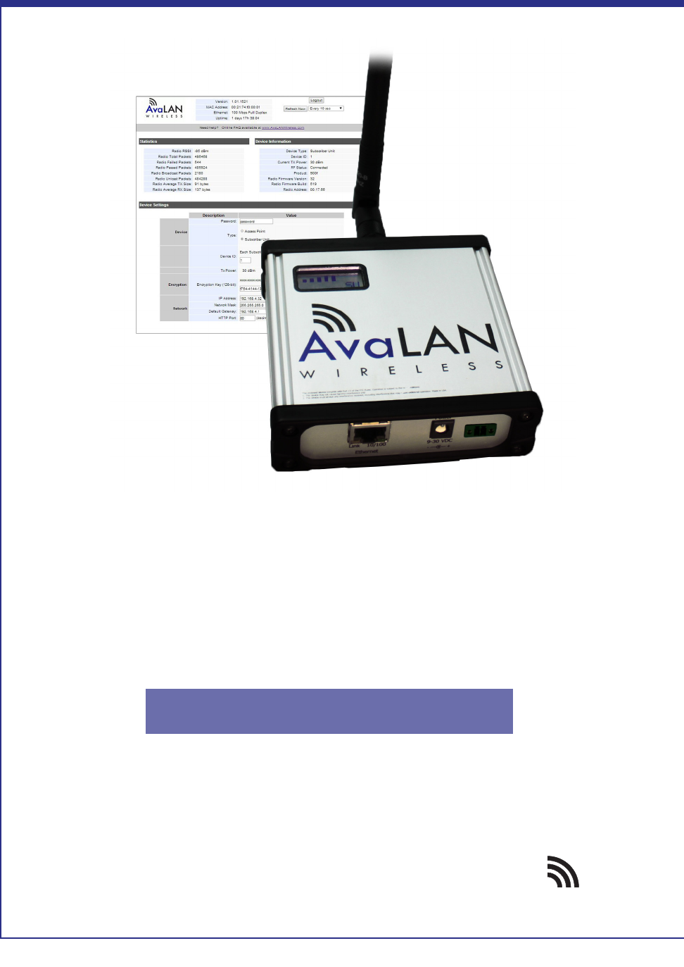
AW900F | AW900F-PAIR User’s Manual 7. The admin page has sections similar to the login page showing radio statistics and device information plus it adds several new sections. The Device Settings section allows setting the network information. Scroll down in the Admin browser page to see these additional sections: 1. A section to be used if an update to the AW900F’s firmware is required 8. On the web browser • Choose Device Type: Access Point or Subscriber Unit.
AW900F | AW900F-PAIR User’s Manual 9. When all of the radios are keyed and operating, connect them to your network and Ethernet devices as desired and cycle the radio’s power to begin normal operation. Now, browser mamagement of the SUs can be performed over the wireless network.
AW900F | AW900F-PAIR User’s Manual LCD Display During boot up: After boot up LCD will display: 1. Current Version Searching for Subscriber radios 2. Radio Address: Link Quality/Active 3. Serial Number Device type: AP or SU 4. IP Address* Technical Support (650) 384-0000 PAGE 12 www.avalanwireless.
AW900F | AW900F-PAIR User’s Manual Limited Warranty This product is warranted to the original purchaser for normal use for a period of 360 days from the date of purchase. If a defect covered under this warranty occurs, AvaLAN will repair or replace the defective part, at its option, at no cost. This warranty does not cover defects resulting from misuse or modification of the product. Technical Support (650) 384-0000 PAGE 13 www.avalanwireless.
AW900F | AW900F-PAIR User’s Manual Technical Specifications PARAMETER RF Data Rate Throughput Frequency Range Transmit Power Receiver Sensitivity Access Scheme Modulation/Spreading Range Browser Management Tools Data Security Operating Environment Mounting Ethernet Data Interface Connectors Power System Power Consumption Package Size Antenna Warranty Certification SPECIFICATION 200 kbps 120kbps total throughput shared between all radios in the group 902.75 MHz to 927.
AW900F | AW900F-PAIR User’s Manual Radio Status Information The Login or Admin pages of the radio’s built-in web browser interface provide many useful pieces of information that let you know how well the wireless link is working: Top of Web Page Version MAC Address Ethernet Uptime Current version of the radio’s Ethernet interface. Radio’s hardware MAC Address. Status of Ethernet connection: 10 Mbps or 100 Mbps, full or half duplex, connected or disconnected.
AW900F | AW900F-PAIR User’s Manual Antenna Alignment Guide Please be sure to consider the following when installing antennae from AvaLAN: Vertical polarization for directional antennas Omni-antenna Figure 1 11 dBi antenna Horizontal polarization for directional antennas Figure 2 Do not aim the omni-antennae directly at each other Technical Support (650) 384-0000 PAGE 16 www.avalanwireless.
AW900F | AW900F-PAIR User’s Manual ATTENTION: When multiple antennas defined as Access Points are installed in one area and face the same direction, antennas should be spaced a minimum of 25 feet apart. When multiple antennas are installed in one area and face different directions, antennas should be spaced a minimum of 15 feet apart. Horizontal polarization 0-deg. separation 45-deg.
AW900F | AW900F-PAIR User’s Manual Transmitter to Reciever Placement If radios are installed either indoors or outdoors at distances closer than recommended, antennas can overpower each other and cause undesired effects. If testing radios within one or two feet, remove both antennas. The radios will still be able to signal each other at close distances. This applies to both indoor and outdoor units.