Arbor Pellet Stove • Horizontal Or Vertical Vent • Freestanding Stove • Mobile Home Approved • Class A Chimney Retrofit • Hearth Stove into Existing Masonry Chimney , Masonry Fireplace, or Z.C. Fireplace Tested and Listed by Omni-Test Laboratories, Inc. Beaverton, Oregon Report # 028-S-77-2 ASTM E1509-2004 - - Please read this entire manual before installation and use of this pellet fuelburning room heater.
Introduction 2 Introduction We welcome you as a new owner of an Arbor pellet heater. In purchasing an Arbor you have joined the growing ranks of concerned individuals whose selection of an energy system reflects both a concern for the environment and aesthetics. The Arbor is one of the finest home heaters the world over. This manual will explain the installation, operation, and maintenance of this pellet-burning heater.
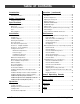
Table of Contents Introduction Operation (continued) Introduction ......................................................2 Important Information .........................................2 Safety Precautions Safety Precautions ............................................4 Specifications Heating Specifications ........................................6 Dimensions.......................................................6 Electrical Specifications......................................6 Fuel.....................
Safety Precautions 4 • Do not operate the heater if you smell smoke coming from the heater. Turn the M ODE switch to "OFF", monitor your heater, and call your dealer. Gas • Contact your local building officials to obtain a permit and information on any installation restrictions or inspection requirements in your area. Notify your insurance company of this heater as well.
Safety Precautions ? • The heater will not operate during a power outage. If a power outage does occur, check the heater for smoke spillage and open a window if any smoke spills into the room. • This heater must be connected to a standard 115 V., 60 Hz grounded electrical outlet. Do not use an adapter plug or sever the grounding plug. Do not route the electrical cord underneath, in front of, or over the heater. • Keep foreign objects out of the hopper.
Specifications 6 Heating Specifications Approximate Maximum Heating Capacity (in square feet)* ........................................800 to 2,250 Sq. Feet Burn Rate (Pounds per Hour)**............................................................................1.7 to 5.5 Maximum Burn Time on Low Burn** ......................................................................29 Hours Hopper Capacity ..............................................................................................
Installation 7 (For Qualified Installers Only) Before You Begin READ THIS ENTIRE MANUAL BEFORE YOU INSTALL AND USE THIS HEATER. FAILURE TO FOLLOW THE INSTRUCTIONS MAY RESULT IN PROPERTY DAMAGE, BODILY INJURY, OR EVEN DEATH. Check with local building officials for any permits required for installation of this pellet heater and notify your insurance company before proceeding with installation.
Installation 8 (For Qualified Installers Only) Clearances - Straight Installation Interior Vertical Vents Through the Wall Installations AA A AA A AA A AAAAAAA AAAAAAA AAAAAAA AAAAAAA AAAAAAA AAAAAAA AAAAAAA AAAAAAA AAAAAAA 3” Minimum 3” Minimum 2” Minimum “Tee” 7” Minimum 6” Minimum AAAAAAAA AAAAAAAA AAAAAAAA AAAAAAAA AAAAAAAA AAAAAAAA AAAAAAAA AAAAAAAA AAAAAAAA AAAAAAAA AAAAAAAA 7” Minimum Floor Protection Clearances - Corner Installation 6” Minimum Through the Wall Vents Interior Vertic
Installation 9 (For Qualified Installers Only) Venting the Pellet Stove • PELLET VENT MUST MAINTAIN A MINIMUM 3" CLEARANCE TO ANY COMBUSTIBLE (INSTALL VENT AT CLEARANCES SPECIFIED BY THE VENT MANUFACTURER). • D O NOT CONNECT THE PELLET VENT TO A VENT SERVING ANY OTHER APPLIANCE OR STOVE. • DO NOT INSTALL A FLUE DAMPER IN THE EXHAUST VENTING SYSTEM OF THIS UNIT.
Installation 10 (For Qualified Installers Only) Pellet Vent Type • Must be 4" diameter Type "L" (except for masonry fireplace installations) - or - connect the vent to a factory built type "A" chimney. All vent joints (including adapters, elbows, etc…) must be sealed with 500° F. RTV silicone. Installing the Pellet Vent Seal each vent section (including adapters, elbows, etc...) by injecting a liberal amount of 500° F. RTV silicone into the gap between sections. V RT F.
Installation 11 (For Qualified Installers Only) Mobile Home Requirements • Outside air is required (used for combustion) - see the directions below. • The heater must be bolted to the floor (Some states do not require this; check with your local building department). See the illustration to the right. • The heater must be grounded to the steel chassis of the mobile home (Some states do not require this; check with your local building department). WARNING: DO NOT INSTALL IN SLEEPING ROOM.
Installation 12 (For Qualified Installers Only) Alcove Installation Requirements When the pellet stove is placed in a location where the ceiling height is less than 7' tall, it is considered an alcove installation. Because of the reduced height, the requirements listed below must be met.
Installation (For Qualified Installers Only) 13 Thermostat Installation ! Do not connect 120 VAC to the thermostat circuit of this heater (do not use a household thermostat used for a wall-board or other electical heater). A thermostat is included with this heater (part # 99300650). Follow the directions below to install. 1 Attach the thermostat wire to the circuit board (see the illustration below). Route the wire through the back of the heater (away from any hot or moving components).
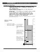
Installation (For Qualified Installers Only) Installation Example: Direct "Through-the-wall" Installation Horizontal Rain Cap 12” Minimum Type "L" Vent A A A A A A A A AAAAAAAA AAAAAAAA AAAAAAAA AAAAAAAA AAAAAAAA AAAAAAAA AAAAAAAA AAAAAAAA AAAAAAAA AAAAAAAA A A A A A A AAA A A A A A A A A A A A A A A A AAAAAAAAAAAA AAAAAAAAAAAAAAAA A AAAAAAAAAAAAA House Shield (used to protect exterior wall from soot discoloration) is HIGHLY RECOMMENDED Wall Thimble (note 3” clearance between vent and combustible
Installation (For Qualified Installers Only) Installation Example: Interior Vertical Installation AAAAAAAA AAAAAAAA AAAAAAAA AAAAAAAA AAAAAAAA AAAAAAAA AAAAAAAA AAAAAAAA AAAAAAAA AAAAAAAA AAAAAAAA AAAAAAAA AAAAAAAAAAAAAAA AAAAAAAAAAAAAAA AAAAAAAAAAAAAAA AAAA AAAAAAAAAAAAAAA AAAA AAAAAAAAAAAAAAA AAAA AAAAAA AAAAAAAAAAAAAAA AAAA AAAAAA AAAAAAAAAAAAAAA AAA AAAAAAA AAAAAAAAAAAAAAA AAA AA AAAAAAA AA AA AA AA AA AA AA AA AA AA AA AA AA AA AA AA AA AA AAAAAAAAAAAAAAAA AA AAAAAAAAAAAAAA AAAAAAAAAAAAAAAA 3” Minim
Installation (For Qualified Installers Only) Installation Example: Class A Chimney Retrofit AAAAAAA AAAAAAA AAAAAAA AAAAAAA AAAAAAA AAAAAAA AAAAAAA AAAAAAA AAAAAAA AAAAAAA AAAAAAA AAAAA AAAAA AAA AAA AAA AAAAAAAAAAAAA AAA AAAA AAA AAAAAAAAAAAAA AAAAAAAAAAAAA AAAA AAA AAAAAAAAAAAAA AAAA AAA AAAAAAAAAAAAA AAAA AAA AAA AAAAAAAAAAAAA AAAAA AAAAA AAAAAAAAAAAAA AAAAA AAAAA AA AA AA AA AA AA AA AA AA AA AA AA AA AA AA AA AA AA AA AAAAAAAAAAAAAAA AAAAAAAAAAAAAAAAA AA AAAAAAAAAAAAA 3” Minimum 2” Minimum “Te
Installation (For Qualified Installers Only) Installation Example: Masonry Fireplace Hearth Stove Vertical Cap “L” Vent Cover Plate (non-combustible) AAAAA AAAA AAAAA AAA AA AA A AA AAAA AAA AA A A AAAAAA AA AAAAAAAAA AAAA AA AA AAA AA AAAA AAAA AA AA AAA AA AAAA AAAAAA AAAA AA AAA AA AA AA AAA AA AA AA AAAA AAA AA AA AAAA AAA AA AA AA AAAA AAA AA AA AAAAA AAAAA AA AA AAAA AA AAAAAA AAAAA AA AA AA AAAA AA AAAAA AAAAA AA AAAA AAAAA AA AA AAAAA AA AA AAA AAAA AA AA AAAAA AAA AAAA AA AA AA AA AAAAA AA AA
Installation (For Qualified Installers Only) Installation Example: Zero-Clearance (Metal) Fireplace Hearth Stove Vertical Cap Storm Collar “L” Vent AAAA AAAA AAAA AAAA “L” Vent Flex Section Cover Plate (non-combustible) one Silic Seal the cover plate with silicone.
Installation 19 (For Qualified Installers Only) Installation Example: Freestanding Masonry Chimney Vertical Cap “L” Vent Cover Plate (non-combustible) Storm Collar AAA AAAA AA AAAA AAA AA AAA AAAAAAA AAAAA AA AAA AA AAA AAA AA AAAAA AA AAA AAAAA AAA AA AAAA AAAAA AA AAA AAAAA AAA AA AAAA AAAAA AA AAAAAAAA AAA AA AAAA AAAAA AAAA AA AAA AAA AA AAAAA AA AAA AAA AA AA AAAAAAAA AAA AA AA AAA AAAAA AAA AA AAAAA AA AAA AAA AA AA AAAAAAAA AAAAA AAAAA AA AAA AAA AA AA AAAAAAAA AAA AA AA AAA AAAAA AAA AA AAAAA
Operation 20 Safety Notice Read this entire manual (especially the "Safety Precautions" on pages 4 and 5) before using this stove. Failure to follow the instructions may result in property damage, bodily injury, or even death. ! Do not unplug the stove to turn it off. This stove relies upon electricity to push the flue gases out the pellet vent – unplugging it may lead to smoke entering your room.
Operation 21 Loading Pellets Lift the hopper lid to its vertical position. Pour pellets into the hopper until full. NOTE: The hopper holds approximately 50 pounds of pellets. To Open the Hopper Lid: Lift the hopper lid from this handle. Pe ll ets AAAAAA AAAAAAAAAA AA AAAAAAAA AAAAAAAAAA AAAAAA AAAAAAAA AAAAAAAAAA AAAAAA AAAAAAAA AAAAAA AAAAAAAAAA AAAAAA AAAAAA AAAAAAAAAA AAAAAA AAAAAA Warning: The front edge of the stove top becomes very hot, do not touch this area below the handle.
Operation 22 Manual Mode Manual mode requires the user to turn the heater on and off manually. H E A T To Start Press the "Manual Start" button. That's it. The stove automatically goes to a medium burn rate and high fan while the igniter starts the fire burning within 10 minutes. During this period the lowest “HEAT OUTPUT” light will flash. If the stove does not start in 30 minutes, the stove turns off.
Operation 23 Auto Mode Auto mode allows you to use a thermostat to control room temperature. The stove automatically turns on when the temperature drops below the thermostat setting. Once the stove reaches operating temperature, the stove then runs at the heat output setting selected. To Adjust Room Temperature (or Start the Stove) Move the thermostat to the heat setting desired. If the room is cooler than the setting, the stove will go through the start-up sequence for approximately 10 minutes.
Operation 24 Restrictor Adjustment The restrictor “fine tunes” your appliance, adjusting the amount of air flowing to the flame. NOTE: the optimal restrictor position will vary over time as soot builds up inside the exhaust system. Not Enough Air If clinkers (ashes that solidify into a clump) develop or the flame appears lazy and slow to blow the ash out of the firepot, pull the restrictor outward until the flame becomes active and the firepot holes remain clean.
Operation 25 Start-Up Sequence This stove utilizes a start-up sequence whenever the mode switch is changed or the heater is started when cold. This is to ensure proper operation through all possible settings and operational states (hot or cold, pellets burning or not burning, etc.). This sequence over-rides all user settings (except the "OFF" position) to set the auger feed rate to medium, the exhaust blower to high, and the igniter on. During this period the lowest “HEAT OUTPUT” light will flash.
Operation 26 Using a Pellet/Corn Mix with This Heater This heater may burn a mixture of corn and wood pellets up to a 50% - 50% proportion by volume. Shelled corn burned in Travis pellet appliances must be clean (free of husk and cob residue) and have a moisture content no greater than 15%. DO NOT BURN A MIX WITH MORE THAN 50% CORN TO WOOD PELLETS. THOROUGHLY MIX THE TWO FUELS TOGETHER TO BE SURE OF AN EVEN BURN RATE.
Maintenance 27 Daily Maintenance (whenever using the stove) Inspect the Burn When burning on high, the flames should be bright orange with embers jumping from the firepot. NOTE: the optimal restrictor position will vary over time as soot builds up inside the exhaust system. See "Restrictor Adjustment" for details. Make Sure Pellets are Not Piling Up If the pellets pile up over the burn pot, turn the mode switch to "OFF".
Maintenance 28 Daily Maintenance (whenever using the stove) - Continued Check Firepot for Clinkers If the flames seem to be coming only from the sides, or are orange/black, turn the heater off and check for clinkers (ashes that solidify into a clump).
Maintenance 29 Daily Maintenance (whenever using the stove) - Continued Door Opening WARNING: Make sure the heater has fully cooled (approximately 25 minutes) before opening the door and conducting service. Open the latch. Swing the doors open. WARNING: Do not swing the doors past 90°. This may cause the doors to strike the body of the stove and cause damage. NOTE: When closing the doors, close the left door first. Then shut the right door and tighten the latch.
Maintenance 30 Bi-Weekly Maintenance (or every 10 bags of pellets) Flyash Removal This heater was designed to allow for easy flyash removal with the included tools. However, to ease maintenance, several pellet stove owners have purchased vacuums specifically made to remove flyash. Furthermore, some of these vacuums are heat-resistant to allow for flyash removal while it is still warm. Do not use a standard vacuum on this appliance (except to clean the pellet dust out of the hopper).
Maintenance 31 Bi-Weekly Maintenance (or every 10 bags of pellets) - continued Clean the Baffles WARNING: Make sure the heater has fully cooled (approximately 25 minutes) before conducting service. HINT: The more often you clean out flyash, the more efficient your heater will burn. The baffles are found along the top of the firebox. The front edge has a slot that slides into a hook on the top of the firebox. The back rests on the back refractory.
Maintenance 32 Bi-Weekly Maintenance (or every 10 bags of pellets) - continued Sweep Ash Into Ashpan WARNING: Make sure the heater has fully cooled (approximately 25 minutes) before conducting service. Remove the two ashdump covers on the floor of the firebox using the included hook tool. Remove the firepot and place it aside. Sweep accumulated flyash through the holes in the firebox floor into the ashpan. Replace the covers and firepot after cleaning. Lift the firepot out of the firebox.
Maintenance 33 Bi-Weekly Maintenance (or every 10 bags of pellets) - continued Check Ashpan, Dispose if necessary WARNING: Make sure the heater has fully cooled (approximately 25 minutes) before conducting service. WARNING: The ashpan must be in place while the heater is in use. Lift up on the ashlip and slide the ashpan forward. AAAAA AAAAA AAAAA AA Twist the ashpan handle clockwise. AA AA A handle is provided on the ashpan to remove the ashes.
Maintenance 34 Yearly Maintenance (or every two tons) The following section details extensive maintenance procedures. We strongly suggest these items be carried out by a trained service technician, possibly by a service agreement set up with your dealer. WARNING: Disconnect the power cord and make sure the heater has fully cooled prior to conducting service. Soot and Flyash: Formation and Need for Removal – The products of combustion will contain small particles of flyash.
Maintenance 35 Yearly Maintenance (or every two tons) - continued Remove the button plugs at the top of the firebox (both sides). Once removed, use the bottle brush to dislodge any flyash from the exhaust channel behind the button plug. Use the bottle brush to clean this channel. Button Plug Use the included bottle brush to remove accumulated flyash from the vertical exhaust channels (both sides). You may need to bend the bottle brush to allow it to access this area.
Maintenance 36 Yearly Maintenance (or every two tons) - continued Clean the Exhaust Blower The exhaust blower cover is held in place with 4 screws. Remove the side cover. Remove the cover plate on the exhaust blower. Clean the area inside the blower, removing all flyash. Remove these 3 nuts to expose the exhaust blower. © Travis Industries Use the bottle brush to disoldge any flyash near the exahust blower and in the horizontal exhaust channel.
Maintenance 37 Yearly Maintenance (or every two tons) - continued Clean the Convection Blower Remove all dust and debris from the convection blower. Take care to prevent damage to the convection blower impellers. Clean the Vent AA AA AA Flyash will deposit along sections that are horizontal. Warning: Make sure the cap is free of debris (especially if it has a screen that could become blocked). AA AA AA Check the vent sections for creosote accumulation (indicating a poorly burning stove).
Maintenance 38 Replacement Parts Door Replacement Parts 6 5 3 1 8 9 7 AAAA AA AAA AAAAAAA AA AAAA AA AAA AAAA AA AAA AAAA AAA AAAA AAA AAAA 4 2 10 ID # 1 3 5 7 9 Description Door, Left Door Gasket Glass Gasket Glass Clip w Screws, Gasket Left Door Handle w Hardware Qty 1 1 1 4 1 Part # ID # 2 4 6 8 10 Description Door, Right Gasket Cement Glass Door Hinge w Pins Right Door Handle w Hardware Qty 1 1 2 4 1 Part # Replacement Parts Description ASHPAN ASSY - COMPLETE - SERVICE PART AUGER DRIVE
Normal Operating Sounds Heat Exchanger Tubes You may hear the heated air being forced through these tubes by the convection fan. Convection Fan The modern high efficiency fan may produce a low hum, particularly on "HIGH". This sound will change as the FAN setting is changed. Exhaust Blower This blower may create a low-pitched hum. This sound will change as the HEAT OUTPUT is altered. Firepot As pellets are fed into the firepot, a light clicking sound may be heard.
Safety Label 40 © Travis Industries 4070806 100-01191_000
Limited 7 Year Warranty 41 To register your TRAVIS INDUSTRIES, INC. 7 Year Warranty, complete the enclosed warranty card and mail it within ten (10) days of the appliance purchase date to: TRAVIS INDUSTRIES, INC., 4800 Harbour Pointe Blvd. SW, Mukilteo, WA 98275. TRAVIS INDUSTRIES, INC. warrants this appliance (appliance is defined as the equipment manufactured by Travis Industries, Inc.
Index 42 "AUGER ON" Light..............................................25 "FAULT" Light ....................................................25 "MANUAL AUGER" Button....................................25 Adjusting the Door Hinge and Latch .......................37 Adjusting the Fan Speed......................................24 Alcove Installation Requirements ..........................12 Auto Mode ........................................................23 Baffle Installation................................