Astoria Pellet Stove • Horizontal Or Vertical Vent • Freestanding Stove • Mobile Home Approved • Class A Chimney Retrofit • Hearth Stove into Existing Masonry Chimney , Masonry Fireplace, or Z.C. Fireplace - - Please read this entire manual before installation and use of this pellet fuelburning room heater. Failure to follow these instructions could result in property damage bodily injury or even death.
Introduction 2 Introduction We welcome you as a new owner of an Astoria pellet heater. In purchasing an Astoria you have joined the growing ranks of concerned individuals whose selection of an energy system reflects both a concern for the environment and aesthetics. The Astoria is one of the finest home heaters the world over. This manual will explain the installation, operation, and maintenance of this pellet-burning heater.
Table of Contents Introduction Operation (continued) Introduction ......................................................2 Important Information .........................................2 Safety Precautions Safety Precautions ............................................4 Specifications Heating Specifications ........................................6 Dimensions.......................................................6 Electrical Specifications......................................6 Fuel.....................
Safety Precautions 4 • Do not operate the heater if you smell smoke coming from the heater. Turn the M ODE switch to "OFF", monitor your heater, and call your dealer. Gas • Contact your local building officials to obtain a permit and information on any installation restrictions or inspection requirements in your area. Notify your insurance company of this heater as well.
Safety Precautions ? • The heater will not operate during a power outage. If a power outage does occur, check the heater for smoke spillage and open a window if any smoke spills into the room. • This heater must be connected to a standard 115 V., 60 Hz grounded electrical outlet. Do not use an adapter plug or sever the grounding plug. Do not route the electrical cord underneath, in front of, or over the heater. • Keep foreign objects out of the hopper.
Specifications 6 Heating Specifications: Approximate Maximum Heating Capacity (in square feet)*.................................800 to 2,250 Sq. Feet Burn Rate (Pounds per Hour)**.......................................................................1.7 to 5.5 Maximum Burn Time on Low Burn** ................................................................67.5 Hours Hopper Capacity............................................................................................
Installation 7 Before You Begin READ THIS ENTIRE MANUAL BEFORE YOU INSTALL AND USE THIS HEATER. FAILURE TO FOLLOW THE INSTRUCTIONS MAY RESULT IN PROPERTY DAMAGE, BODILY INJURY, OR EVEN DEATH. Check with local building officials for any permits required for installation of this pellet heater and notify your insurance company before proceeding with installation.
Installation 8 Clearances - Straight Installation Through the Wall Installations A A A A A A AAAAAAAA AAAAAAAA AAAAAAAA AAAAAAAA AAAAAA AAAAAAAA AAAAAA AAAAAAAA AAAAAA AAAAAAAA AAAAAAAA AAAAAAAA Interior Vertical Vents “Tee” 3” Minimum Floor Protection Clearances - Corner Installation 6” Minimum Through the A AA A AA A AA AAAAAAAAAAAA AAAAAAAAAAAA AAAAAAAAAAAA AAAAA AAAAAAAAAAAA AAAAA AAAAAAAAAAAA AAAAA AAAAAAAAAAAA AAAAA AAAAAAAAAAAA AAAAA AAAAAAAAAAAA AAAAAAAAAAAA AAAAAAAAAAAA AAAAAAAAAAAA AAAA
Installation 9 Venting the Pellet Stove • PELLET VENT MUST MAINTAIN A MINIMUM 3" CLEARANCE TO ANY COMBUSTIBLE (INSTALL VENT AT CLEARANCES SPECIFIED BY THE VENT MANUFACTURER). • DO NOT CONNECT THE PELLET VENT TO A VENT SERVING ANY OTHER APPLIANCE OR STOVE. • DO NOT INSTALL A FLUE DAMPER IN THE EXHAUST VENTING SYSTEM OF THIS UNIT.
Installation 10 Pellet Vent Type • Must be 4" diameter Type "L"(except for masonry fireplace installations) - or - connect the vent to a factory built type "A" chimney. All vent joints (including adapters, elbows, etc…) must be sealed with 500° F. RTV silicone. Installing the Pellet Vent Seal each vent section (including adapters, elbows, etc...) by injecting a liberal amount of 500° F. RTV silicone into the gap between sections. V RT F.
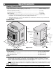
Installation 11 Mobile Home Requirements • Outside air is required (used for combustion) - see the directions below. • The heater must be bolted to the floor (Some states do not require this; check with your local building department). See the illustration to the right. • b Use the lag bolts (used to secure the stove to the pallet) to screw the pedestal to the floor.
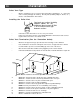
Installation 12 Alcove Installation Requirements When the pellet stove is placed in a location where the ceiling height is less than 7' tall, it is considered an alcove installation. Because of the reduced height, the requirements listed below must be met. • Minimum height is 60" • Maximum depth is 48" • Minimum width is 46" • Minimum clearance of 9" on each side and 3" on back Baffle Installation Install the baffles included with the stove (see page 29 for details).
Installation 13 Installation Example: Direct "Through-the-wall" Installation Horizontal Rain Cap Type "L" Vent Outside Air 12” Minimum AAAAAAAAAAAAA A AAAAAAAAAAAAA AA A AAAAAAAAAAAAA AA A AAAAAAAAAAAAA A AAAAAAAA A AAAAAAAA A AAAAAAAA A AAAAAAAA AAAAAA A AAAAAAAA AAAAAA A AAAAAAAA AAAAAA A AAAAAA AAAAAAAA A AAAAAAAA A AAAAAAAA AA A AA A AA A A AA A AA A AA A AA A AA A AA A AA A AAAAAAAAAAAAAAA AA A AAAAAAAAAA AAAAAAAAAAAAAAA House Shield - prevents discoloration to outside of home - HIGHLY RECOMMEND
Installation 14 Installation Example: Interior Vertical Installation AAAAAAAAAAAA A AAAAAAA A AAAAAAA A AAAAAAA A AAAAAAA A AAAAAAA A AAAAAAA A AAAAAA AAAAAA AAAAAAA A AAAAAA AAAAAAA AAAAAAA AAAAAAA AAAAAAA 2” Minimum 3” Minimum “Tee” Outside Air (optional) Type "L" Vent 9” Minimum Floor Protection 6” Minimum Vertical Cap AAAAAAAAAAAAAA AAAAAAAAAAAAAA AAAAAAAAAAAAAA AAAA AAAAAAAAAAAAAA AAAA AAAAAAAAAAAAAA AAAA AAAAAAA AAAA AAAAAAAAAAAAAA AAAAAAA AAAAAAAAAAAAAA AAA AAAAAAA AA AA AA AA AA AA AA AA
Installation 15 Installation Example: Class A Chimney Retrofit AAAAAAAAAAAAAAA AA AAAAAAAAA AA AAAAAAAAA AAAAAAAAA AA AA AAAAAAAAA AA AAAAAAAAA AA AAAAAAAAA AA AAAAAAAAA AA AAAAAAAAA AAAAAAA AA AAAAAAAAA AAAAAAA AA AAAAAAAAA AAAAAAA AAAAAAAAA AAAAAAAAA AAAAAAAAA AAAAAA AAAAAA AAAA AAAAAA AAAA AAAA AAAA AAAA AAAAAAAAAAAAAAAA AAAAAAAAAAAAAAAA AAAA AAAAAAAAAAAAAAAA AAAA AAAAAAAAAAAAAAAA AAAA AAAAAAAAAAAAAAAA AAAA AAAAAAAAAAAAAAAA AAAA AAAAAAAAAAAAAAAA AAAAAA AAAA AAAAAA AAAAAAAAAAAAAAAA AAAAAA A AAAAAA A AA
Installation 16 Installation Example: Masonry Fireplace Hearth Stove Vertical Cap “L” Vent Cover Plate (non-combustible) AAAAA AAAA AAAAA AAA A AA AAA AAAA AAAA AA AA AAAAAA AA AAA AA AAAA AA AAAA AA AAA AA AAAA AAAA AA AA AAA AA AAAA AAAAAA AAAA AA AAA AA AA AAAA AA AAA AA AA AA AAAA AAA AA AAAAA AA AA AA AA AAAA AAA AA AAAAA AAAA AAA AA AA AA AAAAA AA AA AAAA AA AAAAA AAAA AA AA AA AAAAA AAAAAA AAAAA AAAAA AA AA AA AA AAA AAAA AA AAAAA AAA AAAA AAAAA AA AA AA AA AAAAA AA AA AAAAA AA AA AAA AA AAAAA A
Installation 17 Installation Example: Zero-Clearance (Metal) Fireplace Hearth Stove Vertical Cap Storm Collar “L” Vent Cover Plate (non-combustible) one Silic Seal the cover plate with silicone.
Installation 18 Installation Example: Freestanding Masonry Chimney Vertical Cap “L” Vent Cover Plate (non-combustible) AAAA AAAA AAAA AAA AA AA A A AA AAAA AAA AA A A AA AA AAAA AA AA AAA AAAA AA AA AAAA AA AA AAA AAAA AAAA AA AA AAA AA AAAAAA AAA AA AA AAAA AA AA AA AA AAAA AA AA AA AA AAAA AA AA AAAA AA AA AA AA AA AAAA AA AA AA AAAA AA AA AA AA AA AAAA AA AA AA AAAA AA AA AA AA AA AA AAAA AA AA AA AAAA AA AA AA AA AA AA AA AA AA AA AA AA AA AAAAAA AA AA AA AA AAAAAA AA AA AA AA AAAAAA AA AA AA AA AAA
Operation 19 Safety Notice Read this entire manual (especially the "Safety Precautions" on pages 4 and 5) before using this stove. Failure to follow the instructions may result in property damage, bodily injury, or even death. ! Do not unplug the stove to turn it off. This stove relies upon electricity to push the flue gases out the pellet vent – unplugging it may lead to smoke entering your room.
Operation 20 Loading Pellets Lift the hopper lid to its vertical position. Pour pellets into the hopper until full. NOTE: The hopper holds approximately 115 pounds of pellets. To Close the Hopper Lid: lift the lid, pull this tab forward, then lower the lid down. To Open the Hopper Lid: These notches allow lift the hopper lid from this handle. you to open the hopper lid to the level you wish.
Operation 21 Manual Mode Manual mode requires the user to turn the heater on and off manually. H E A T To Start Press the "Manual Start" button. That's it. The stove automatically goes to a medium burn rate and high fan while the igniter starts the fire burning within 10 minutes. During this period the lowest “HEAT OUTPUT” light will flash. If the stove does not start in 30 minutes, the stove turns off.
Operation 22 Auto Mode Auto mode allows you to use a thermostat to control room temperature. The stove automatically turns on when the temperature drops below the thermostat setting. Once the stove reaches operating temperature, the stove then runs at the heat output setting selected. To Adjust Room Temperature (or Start the Stove) Move the thermostat to the heat setting desired. If the room is cooler than the setting, the stove will go through the start-up sequence for approximately 10 minutes.
Operation 23 Restrictor Adjustment The exhaust restrictor “fine tunes” your appliance, adjusting the amount of air flowing to the flame. NOTE: the optimal restrictor position will vary over time as soot builds up inside the exhaust system. Not Enough Air: If clinkers develop or the flame appears lazy and slow to blow the ash out of the firepot, pull the restrictor outward until the flame becomes active and the firepot holes remain clean.
Operation 24 Start-Up Sequence This stove utilizes a start-up sequence whenever the mode switch is changed or the heater is started when cold. This is to ensure proper operation through all possible settings and operational states (hot or cold, pellets burning or not burning, etc.). This sequence over-rides all user settings (except the "OFF" position) to set the auger feed rate to medium, the exhaust blower to high, and the igniter on. During this period the lowest “HEAT OUTPUT” light will flash.
Maintenance 25 Daily Maintenance (whenever using the stove) Inspect the Burn When burning on high, the flames should be bright orange with embers jumping from the firepot. NOTE: the optimal restrictor position will vary over time as soot builds up inside the exhaust system. See "Restrictor Adjustment" for details. Make Sure Pellets are Not Piling Up If the pellets pile up over the burn pot, turn the mode switch to "OFF".
Maintenance 26 Daily Maintenance (whenever using the stove) - Continued Check Firepot for Clinkers If the flames seem to be coming only from the sides, or are orange/black, turn the heater off and check for clinkers.
Maintenance 27 Door Opening WARNING: Make sure the heater has fully cooled (approximately 25 minutes) before opening the door. Phillips Screwdriver Bracket (attached to side of heater) Pawl Door Frame AAAAAAAA AAAA AAAAAAAA AAAA AAAAAAAA AAAAAAAA AAAAAAAA AAAAAAA AAAA AAAAAAA AAAAAAA AAAAAAA Lock Nut When securing the door, make sure the pawl fits over the bracket before tightening. NOTE: Do not overtighten the pawl. This can permanently damage the latch and prematurely wear out the door gasket.
Maintenance 28 Bi-Weekly Maintenance (or every 10 bags of pellets) Clean the Heat Exchange Tubes Open the hopper lid. WARNING: The front edge of the hopper lid becomes very hot, do not touch the area below the handle. AAAAAAAA AAAAAA AAAAAA AAA AAAAAAAA AAAAAA AAA AAAAAA AAAAAAAA AAAAAA AAAAAA AAAAAAAA AAAAAA AAAAAA Store the scraper rod tool by hanging it on the hanger on the back of the stove.
Maintenance 29 Bi-Weekly Maintenance (or every 10 bags of pellets) - Continued Clean the Baffles Use both hands to lift each baffle up and forward. Then tilt the baffle downward to remove any flyash that may have accumulated on top of the baffle. N O T E: you do not need to remove the baffle from the firebox. The firebox baffles install on ledges at the top of the firebox. The two tabs (at the outside back corners) insert into notches at the right and left rear corners of the firebox walls.
Maintenance 30 Sweep Ash Into Ashpan HINT: The more often you clean out the flyash, the more efficient your heater will burn. WARNING: The firebox becomes very hot during operation. Let the stove cool completely before conducting service. a Lift it up and away from the firebox. Repeat for the opposite side. b Swing the side ash trap door up. Ash Trap Door c Lift the firepot out of its holder.
Maintenance 31 Bi-Weekly Maintenance (or every 10 bags of pellets) - Continued Check Ashpan, Dispose if necessary The ash pan has a built in handle to ease transportation of the ashes. AAAAAAA AAAAAAA AAAAAAA AAAAAAA AAA AAA AAAAAAA AAAAAAA NOTE: When replacing the ash pan make sure it is pushed all the way in. Disposal of Ashes – Ashes should be placed in a metal container with a tight fitting lid.
Maintenance 32 Yearly Maintenance (or every two tons) WARNING: Disconnect the power cord prior to conducting service. The following section details extensive maintenance procedures. We strongly suggest these items be carried out by a trained service technician, possibly by a service agreement set up with your dealer. Soot and Flyash: Formation and Need for Removal – The products of combustion will contain small particles of flyash.
Maintenance 33 Yearly Maintenance (or every two tons) - Continued Clean the Exhaust Blower (make sure the stove is cool and unplugged) a b Open the hopper lid Remove the six screws holding the exhaust blower motor in place. and remove the screw holding the 11/32" Socket left door in place. Remove the knob on the restrictor rod. Swing the left side panel open. Phillips Screwdriver c Pull the motor out (be careful not to damage the wiring or blades replace gasket if it is damaged).
Maintenance 34 Yearly Maintenance (or every two tons) - Continued Door Seal ! • Air leaks into the firebox will decrease the stove's performance greatly, leading to excessive sooting, inefficient burning, and perhaps a malfunction. The door gasket must contact the entire perimeter of the door and create an airtight seal. To verify this, open the door, hold a dollar bill against the body of the heater, close the door, and secure the latch.
Maintenance 35 Adjusting the Door Hinge and Latch • The door hinge and door latches may be adjusted to pull the door closer to the body. The illustration below details how to adjust these components. NOTE: Make sure to read the section "Door Alignment" on the previous page before adjusting the door. Open the hopper lid and remove the two screws holding the side doors in place. Latch Adjustment Loosen the lock nut and twist the pawl (clockwise to tighten, counter-clockwise to loosen).
Maintenance 36 Check for Air Leaks Around the Door, Glass, and Ashpan ! • • • Air leaks into the firebox will decrease the stove's performance greatly, leading to excessive sooting, inefficient burning, and perhaps a malfunction. Inspect the door gasket to make sure it is fully attached. Use stove gasket cement to re-attach if necessary. If the door gasket is worn or flattened, replace. If the glass is cracked, replace. The glass is held in place by glass clips that are underneath the airwash brackets.
Normal Operating Sounds 37 Exhaust Blower This blower may create a low-pitched hum. This sound will change as the HEAT OUTPUT is altered. Auger Motor When feeding pellets, you may hear the intermittent buzz of this motor running. Heat Exchanger Tubes You may hear the heated air being forced through these tubes by the convection fan. Convection Fan The modern high efficiency fan may produce a low hum, particularly on "HIGH". This sound will change as the FAN setting is changed.
Safety Label 38 WARNING - DO NOT REMOVE OR COVER THIS LABEL Listed Pelletized Solid Fuel Burning Appliance Also for Use in Mobile Homes Model: Astoria PS Report No. 028-S-42-2 Serial No: Tested to: ASTM E, 1509-95, Room Heater Pellet Burning Type (UM) 84 HUD Electrical Rating: 115V, 60Hz, 3 Amp; Start 3 Amps, Run 1.5 Amps Maximum Input Rating: 5.5 lbs (2.
Limited 7 Year Warranty 39 To register your TRAVIS INDUSTRIES, INC. 7 Year Warranty, complete the enclosed warranty card and mail it within ten (10) days of the appliance purchase date to: TRAVIS INDUSTRIES, INC., 4800 Harbour Pointe Blvd. SW, Mukilteo, WA 98275. TRAVIS INDUSTRIES, INC. warrants this gas appliance (appliance is defined as the equipment manufactured by Travis Industries, Inc.
Optional Equipment 40 Thermostat (Part # 99300650) ! Do not connect 120 VAC to the thermostat circuit of this heater (do not use a household thermostat used for a wall-board or other electical heater). 1 2 Attach the thermostat wire to the circuit board (see the illustration to the right). Route the wire through the back of the heater (away from any hot or moving components). Determine a location for the thermostat that is within range of the 20' length of thermostat wire.
Optional Equipment 41 Remote Thermostat Follow the instructions included with the remote thermostat for installation. Using the Remote Thermostat The remote thermostat has a 1 to 2 minute lag time between the time the thermostat is turned up and the heater turns on. Included with the remote thermostat is a set of instructions that details the operating characteristics of this optional component. Pellet Log (part # 98900126) ! Make sure the heater has fully cooled before installation.
Index 42 Adjusting the Fan Speed......................................23 Air Leaks..........................................................36 Alcove Installation Requirements ..........................12 Ashpan (Opening and Disposing Ashes) .................31 AUGER ON Light................................................24 Auto Mode ........................................................22 Bi-Weekly Maintenance (or every 10 bags pellets) ....28 Blower (Exhaust Blower Cleaning) .........................