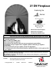
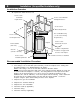
21 DV Fireplace Featuring the Burner Tested and Listed by OMNI-Test Laboratories, Inc. Beaverton, Oregon Report # 028-S-53-5 ANSI Z21.88 • Built-In Direct Vent Fireplace • Natural Gas or Propane • Residential or Mobile Home WARNING: If the information in these instructions is not followed exactly, a fire or explosion may result causing property damage, personal injury or loss of life. - Do not store or use gasoline or other flammable vapors and liquids in the vicinity of this or any other appliance.
Introduction Introduction We welcome you as a new owner of a 21 DV gas fireplace. In purchasing this fireplace you have joined the growing ranks of concerned individuals whose selection of an energy system reflects both a concern for the environment and aesthetics. It is one of the finest home heaters the world over. This manual will explain the installation, operation, and maintenance of this fireplace.
Table of Contents Introduction and Important Information Finalizing the Installation Introduction ......................................................2 Glass Frame Removal and Installation .................28 Log Set Installation............................................30 Steps for Finalizing the Installation.......................32 Pilot Flame Inspection .......................................32 Air Shutter Adjustment .......................................32 Face Installation and Removal ........
Safety Precautions IF YOU SMELL GAS: Do not light any appliance Extinguish any open flame Do not touch any electrical switch or plug or unplug anything Open windows and vacate building Call gas supplier from neighbor's house, if not reached, call fire department This unit must be installed by a qualified installer to prevent the possibility of an explosion. Your dealer will know the requirements in your area and can inform you of those people considered qualified.
Safety Precautions AA A A AAA AA AA AA AA AAA AA AA AA AA A Do not place clothing or other flammable items on or near the heater. Because this heater can be controlled by a thermostat there is a possibility of the heater turning on and igniting any items placed on or near it. The viewing glass should be opened only for lighting the pilot or conducting service. Do not operate with cracked, broken, or removed glass.
Features and Specifications Features • • • • • • • • Installation Options • • • • • • • Works During Power Outages (millivolt system) High Efficiency Optional Thermostat or Remote Control Realistic "Wood Fire" Look Quiet Blower for Effective Heat Distribution Convenient Operating Controls Variable-Rate Heat Output Low Maintenance Heating Specifications Approximate Heating Capacity (in square feet)* Maximum BTU Input Per Hour Minimum BTU Output on Low Steady State Efficiency** (with blowers on) AFUE (
Installation (for qualified installers only) Installation Warnings • Failure to follow all of the requirements may result in property damage, bodily injury, or even death. • This heater must be installed by a qualified installer who has gone through a training program for the installation of direct vent gas appliances. • This appliance must be installed in accordance with all local codes, if any; if not, follow ANSI Z223.1 and NFPA 54(88).
Installation (for qualified installers only) Installation Overview • A AA AA A AA A AA A AAA AA A AA AA A AA A AAAA AAA AA A AA AAA AA A AA AA A AA A AAAA AAA AA A AA AAA AA AA A AA A AA AA A AA A AA AAAAAAAA AA AA AA A AA A A AA A AA AAA AA AA AA A AA A AA AAAAA A AA A AA A AA AAA AA AAAAA A AA AA A AA A AA AA A AA A AA AAA AA AA AA A AA A AA A AA A AA A AA AAA AA A AA AA A AA A AA AA A AA A AA AAA AA AA A AA A AA A AA A AA A AA AAA AA A AA A AA A AA AA A AAA AA A AA A AAA All requirements below must
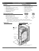
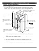
Installation (for qualified installers only) Fireplace Placement Requirements Minimum Framing Dimensions The fireplace requires a 1/2" space between the fireplace and the framing members (or other materials) along the sides and back of the fireplace. The stand-offs (and nailing brackets) may contact the framing members but no material may be placed into the 1/2" space. 1/2" Clearance to the front, 0" to the sides, 1" below, 48" Min. and 2" above the vent to combustibles.
Installation (for qualified installers only) Nailing Brackets There are two nailing brackets on the sides of the fireplace. Follow the directions below to prepare the nailing brackets. Once in place, nail or screw the nailing brackets to the framing. 1/2” Facing TOP VIEW Framing For installations using 1/2” facing (1/2” drywall or other facing) fold the larger tab out 90°.
Installation (for qualified installers only) Corner Installations A typical 45° installation uses the minimum framing dimensions shown in the illustration to the right (NOTE: all clearances still apply). The recommended dimensions shown to the right allow additional space, easing gas line and electrical connections. 22-1/4" Min. 24-7/8" Recommended AAAAAAAAAAAA AA AAAAA AA A AAAAAAAAA AAAAA AAA A AAAAA AA AAAAA AA A AA A AA A AA AA A AA AA A AAA A 5-1/2" Min. 6-1/2" Recommended Min.
Installation (for qualified installers only) Gas Line Requirements MASSACHUSETTS INSTALLATIONS - WARNING: THIS PRODUCT MUST BE INSTALLED BY A LICENSED PLUYMBER OR GAS FITTER WHEN INSTALLED WITHIN THE COMMONWEALTH OF MASSACHUSETTS. OTHER MASSACHUSETTS CODE REQUIREMENTS: • Flexible connector must not be longer than 36 inches. • Shutoff valve must be a “T” handle gas cock. • Only direct vent sealed combustion products are approved for bedrooms or bathrooms.
Installation (for qualified installers only) Optional Gas Line Location a Remove the two screws near the b gas inlet (save these screws). Remove the cover plate on the bottom of the fireplace (save these nuts). Phillips Screwdriver HINT: remove the control cover for easier access. 5/16" Wrench c Position the gas inlet assembly over the hole in d the baseplate (do not secure at this time). Secure the gas inlet assembly using the screws removed in step “a”.
Installation (for qualified installers only) Electrical Line Connection 1/4" Nutdriver b a Remove the cover Insert the sheathed cable from the power source through this cable clamp. Once the wires are attached, tighten the clamp to secure the cable. from the fireplace junction box. Electrical Connector Standard Screwdriver WARNING: Make sure power is off from the power lead before conducting any wiring.
Installation (for qualified installers only) Vent Requirements • The gas appliance and vent system must be vented directly to the outside of the building, and never be attached to a chimney serving a separate solid fuel or gas-burning appliance. Each direct vent gas appliance must use it's own separate vent system. Vent Clearances • The vent must maintain the required clearance to combustible materials to prevent a fire. Do not fill air spaces with insulation.
Installation (for qualified installers only) Vent Installation • Slide the vent sections together and turn 1/4 turn until the sections lock in place. • Screws are not required to secure the vent. However, three screws may be used to secure vent sections together if desired. • High temperature sealant is recommended at the appliance starter section connection (use high-temperature silicone or Mill-Pac®).
Installation (for qualified installers only) Approved Vent Configurations Restrictor Position A vent restrictor is built into the appliance to adjust the flow rate of exhaust gases. This ensures proper combustion for all vent configurations. Depending upon the vent configuration, you may be required to adjust the restrictor position. The charts for acceptable vent configurations detail the correct vent restrictor position.
Installation (for qualified installers only) Vent Configurations with Vertical Termination A maximum of 3 elbows may be used. • 8" or 6-5/8" diameter vent may be used. 40' (max) Restrictor Position # 6 35 feet 30 feet 25 feet NOTE: Two 45° elbows may be used. 20 feet 15 feet 10 feet 6' (min) 5 feet 5 feet 14' (max) • 10 feet The termination must fall within the shaded area shown in the chart. Use the indicated restrictor position.
Installation (for qualified installers only) • • If using 6-5/8" diameter vent, a minimum 12" vertical rise is required. The termination must fall within the shaded area shown in the chart. Use the indicated restrictor position. 14 feet (max) 10 feet 14' (max) 10 feet Use a single 90° elbow (NOTE: an additional 45° elbow may be used on the horizontal run).
Installation (for qualified installers only) Termination Requirements NOTE: Measure all clearances from the nearest edge of the exhaust hood. A Minimum 9" clearance from any door or window B Minimum 12" above any grade, veranda, porch, deck or balcony C Minimum 3-3/8" from outside corner walls D Minimum 0" from inside corner walls E Minimum 11" clearance below unventilated soffits or roof surfaces Roof Surface 11” Min. 6” Min.
Installation (for qualified installers only) Hearth Requirements NOTE: Looking Glass and Wilmington Faces require a raised fireplace - see "Dimensions" for details. Floor Mounted Fireplaces Do not build a hearth or other item above the baseplate (this area must remain clear for the access door).
Installation (for qualified installers only) Facing Requirements NOTE: The combustible area above the facing must not protrude more than 3/4" from the facing. If it does, it is considered a mantel and must meet the mantel requirements listed in this manual. Face Dimensions Face Arched Faces Bungalow, T. of L. Vict.
Installation (for qualified installers only) Facing - Fireplace Details Facing - Top View Fireplace AAA AAAAA AAAAA AAAAAAA AA Face 1/2" Nailing Bracket A 1/2" White Tape Gasket (attached to fireplace) Facing - Side View Fireplace AAAAAAA AAAAAAA AAAAAAA AAAAAAA AAAAAAA A AA AA A AA A AA AA AA AA Face Gasket Wall Trim (1/16" thick) 1" 3/8" 1/8" Wall Trim © Travis Industries 4040830 100-01143
Installation (for qualified installers only) Facing Detail – Drywall Facing Recommended Order of Installation We recommend installing the facing (drywall, tile) under the notch at the front of the fireplace c (“a”) - then install the sides and top (“b” and “c”) b NOTE The facing tucks under the notch at the front of the fireplace a (3/8” above the base of the fireplace).
Installation (for qualified installers only) Facing Detail – Tile Facing NOTE: Make sure to use the correct nailing bracket for this type of facing (see “Nailing Bracket” for details). For this example the facing is 7/8" thick (3/8" tile plus 1/2" drywall). The framing is positioned 1" behind the front of the fireplace. Framing Top View - Tile Facing Fireplace Drywall NOTE: When installed, there must be a minimum 1/8” gap between the face and facing.
Installation (for qualified installers only) Facing Detail –Facing Over 1” Thick (Brick) WARNING: Any facing that extends in front of the faceplate on the sides or top must be noncombustible. NOTE: A 3/8” gap is required above the face for face installation. Framing Top View Fireplace Arched Face Thick Facing Template Part # 225-20040 The Arched Face Thick Facing Template is a separate component that is required when using an arched face with facing that extends beyond the face (e.g.
Installation (for qualified installers only) Mantel Requirements • The combustible area above the facing must not protrude more than 3/4" from the facing. If it does, it is considered a mantel and must meet the mantel requirements listed below. • Use the table below to determine the maximum mantel depth allowed. For example, if a 6” mantel is used, it must be a minimum of 6-1/2” above the face.
Finalizing the Installation Glass Frame Removal and Installation Warning: The appliance must be completely cool before removing the glass. Warning: Do not strike or slam the glass. a Spring Pin Open the four latches holding the glass frame in place (start with the two below Top of Firebox the glass) - follow the directions shown to the right. Insert the 1/4” key into the spring pin. Glass Twist 1/4 turn. Glass Frame b Lift the glass frame up and pull it forward to remove.
Finalizing the Installation Glass Frame Removal and Installation (continued) The spring pin can come loose from the latch assembly. This occurs when it is turned 1/4 turn when it is disengaged. Follow the directions below to re-install the spring pin if it becomes loose. To re-install the spring pin, first insert this end into a 1/4” key. NOTE: The spring pins can be installed with the glass frame in place or removed. Insert the spring pin into this bracket with the pins aligned vertically.
Finalizing the Installation Log Set Installation STEP A – Rear Log Installation Make sure the "cut out" on the bottom of the log installs over the pilot assembly. The rear log rests against the back and left side of the firebox walls. Push on the bottom of the log to insure it sits upright. NOTE: This notch here is for the pilot hood. Make sure the log is correctly aligned so the notch allows the flame to travel from the pilot hood to the burner holes.
Finalizing the Installation STEP B – Twig, Vertical Log, and Ember Installation Place the twig so the pin on the rear log inserts into the hole on the twig. Place the upright log as shown. When installed the top is parallel with the burner and there is a gap under the right "leg". Place the ember chunks along the perimeter of the burner (do not place over the burner holes). Preparing the Rock Wool: AAA AAA The rock wool comes in one clump. Tear off “dime” sized clumps and flatten.
Finalizing the Installation Steps for Finalizing the Installation 1. Remove the glass (see page 28). NOTE: If using propane (LP) convert the appliance prior to installing the logs. 2. We recommend you purge the gas line at this time (with the glass removed). This allows gas to be detected once it enters the firebox, ensuring gas does not build up. 3. Turn on the gas to the fireplace. Turn on gas to the heater. Leak test all gas joints prior to starting the appliance. Start the pilot.
Finalizing the Installation FINE TUNING THE EMBER-FYRE™ BURNER Each installation is affected by altitude, vent configuration, and fuel quality. Because of this, the restrictor and air shutter may need to be fine tuned to each installation. Follow the hints below to finetune the burner for optimum performance and aesthetics. Restrictor Hints: Set the restrictor to the position suggested in the vent configuration table (see page 17). Turn the heater on and allow it to reach full temperature (15 min.).
Finalizing the Installation 8. Replace the glass. 9. Attach the face following the directions below (see the directions included with the face for full details). Face Installation and Removal The face has hooks that hold it in place. Make sure the face locks in place when installing. b Lift and rotate the face forward until the top brackets lock into the upper slots. a Tilt the face back and insert the bottom brackets into the lower slots until they lock in place.
Operation 35 Before You Begin • Read this entire manual before you use your new fireplace (especially the section "Safety Precautions" on pages 4 & 5). Failure to follow the instructions may result in property damage, bodily injury, or even death. Location of Controls The Pilot Flame can be found below the back log. ON/OFF Switch Blower Control An instruction card for operating the fireplace is attached to the inside of the fireplace here. Replace it for easy reference.
Operation Starting The Pilot Flame a The pilot flame is required to ignite the main burners (it also plays a safety role). It should be left on once lit. It will stay lit unless the gas control valve is turned to "OFF". However, the pilot will go out if the gas is shut off, the propane tank runs out (or low) or if the stove malfunctions. If the pilot turns off frequently, call your dealer for information.
Operation 37 Starting the Fireplace for the First Time • Burn the heater at a high setting with the blower off for an extended period (up to 48 hours). This will cure the painted surfaces. Fumes from the paint curing and oil burning off the steel will occur. This is normal. We recommend opening a window to vent the room. • Condensation may appear on the glass each time you start the fireplace - this is normal. • Blue Flames will occur on the fireplace when it first comes on.
Operation Adjusting the Blower Speed The blower helps transfer heat from the heater into the room. It will not turn on until the heater is up to temperature (approximately 10 minutes after starting). See the illustration below for instructions on adjusting the blower speed. OFF Turn the dial all the way counter-clockwise until it clicks off. LOW HIGH The high position is all the way counter-clockwise, without clicking off. Turn the dial all the way clockwise.
Maintenance Maintaining Your Fireplace's Appearance Fingerprints or other marks left on the optional gold surface may become etched in place if they are not wiped clean prior to turning the fireplace on. Clean the gold with denatured alcohol and a soft cloth (with the fireplace cool). Other cleaners may leave a film that may become etched into the gold. Yearly Service Procedure • Failure to inspect and maintain the fireplace may lead to improper combustion and a potentially dangerous situation.
Maintenance Troubleshooting Table Problem: Pilot Will Not Light Main Burners Will Not Start Remote Control Does Not Work Thermostat Does Not Work Fireplace Will Not Possible Cause: Don't Call for Service Until You: A gas shut off valve is turned off Check all gas shut off valves The gas control knob isn't turned to "PILOT" See "Starting the Pilot Light" Step C The valve control knob isn't pushed in See "Starting the Pilot Light" Step C The igniter wasn't pressed repeatedly See "Starting t
Maintenance How this Fireplace Works This fireplace was designed with safety as the primary concern. Many of the components inside this fireplace are for safety purposes. Therefore, only certified gas service technicians should service this fireplace. What Turns the Main Burners On and Off When heated, the thermopile generates electricity (a very small amount measured in "Millivolts"). This electricity is used to operate the main burners.
Maintenance Wiring Diagram Thermocouple Millivolt Wiring (for gas control valve) Thermopile Piezo Igniter On/Off Switch Red AA Brown Copper Co-Axial Wire Orange Red Spark Electrode White 120 Volt Wiring 3 Black Power In Molex Connector Ground (green) Power Supply Optional Remote Control Optional Thermostat Hot (black) Common (white) Pilot Hood White 6 9 1 5 Green 8 11 Ground (attached to stove) 3 Remote Control Molex Connector 2 4 7 9 1 10 4 7 10 Optional Blower White B
Report No. 028-S-53-5 Certified for USA Bed & Breakfast Vented Gas Fireplace Heater Tested to: ANSI Z21.88b-2001 “Vented Gas Fireplace Heater” and UL 307b-1995 “Gas Burning Heating Appliances for Manufactured Homes”. VENTED GAS FIREPLACE HEATER – NOT FOR USE WITH SOLID FUEL This appliance must be installed in accordance with local codes, if any; if none, follow the National Fuel Gas Code, ANSI Z223.1. This vented gas fireplace heater is equipped at the factory for use with natural gas.
Warranty To register your TRAVIS INDUSTRIES, INC. 7 Year Warranty, complete the enclosed Warranty card and mail it within ten (10) days of the appliance purchase date to: TRAVIS INDUSTRIES, INC., 4800 Harbour Pointe Blvd. SW, Mukilteo, WA 98275. TRAVIS INDUSTRIES, INC. warrants this gas appliance (appliance is defined as the equipment manufactured by Travis Industries, Inc.
Optional Equipment (for qualified installers only) 45 LP Conversion Instructions Install the conversion kit prior to installing the gas line to ensure proper gas use. 1 Remove the glass (see page 28). Remove the logs and coals (if installed - page 30) 2 Remove the burner (see illustration below). a b Lift up on the left side of the burner, then slide the burner to the left and up to remove. Lift the pilot hood off the pilot assembly (you may need to pull hard to remove).
Optional Equipment 3 (for qualified installers only) Follow the directions below to replace the orifice. a Slide the air shutter all the way to the left. AA AA A AA AA Burner Orifice Manifold The new LP orifice has “56” stamped on it. d 56 Use a 1/2” open end wrench to unscrew the burner orifice. NOTE: Screw the LP orifice in so the orifice shoulder protrudes 5/16” (indicating full insertion). 5/16” 4 49 1/2" Wrench e Apply thread sealant to the new orifice and install.
Optional Equipment (for qualified installers only) a 5 Install the logs and embers. c Remove and discard the three screws using a slotted screwdriver of Torx T-20. Install the LP regulator. Use the screws included with the LP regulator. Tighten to approximately 25 Lbs. torque. 6 Replace glass and face. 7 Remove the regulator from the front of the gas control valve. Replace with the propane regulator, using the new gasket and screws included with the regulator.
Optional Equipment (for qualified installers only) Firebox Liner WARNING Turn off gas to the appliance and make sure it has fully cooled prior to conducting service. NOTE: The firebox liner is fragile – take care to prevent damage. NOTE: The firebox liner leaves a slight white residue when touched – make sure to clean the area and your hands after handling the liner. 1 Remove the face, glass, and burner. 2 Follow the directions below to remove and discard the steel liner.
Optional Equipment (for qualified installers only) 3 49 Install the liner following the directions below. (a) Tilt the liner forward and at a slight angle as you insert it into the firebox. Place the bottom left corner into the firebox first. (b) As you insert the liner, make sure the liner goes behind the pilot assembly. (c) The top of the liner will be very tight along the top – carefully rotate and tilt the liner into place.
Index Air Shutter Adjustment ........................................32 Blower Operation.................................................38 Cap (Termination) Requirements...........................20 Clearances ........................................................9 Condensation on Glass (see "Starting Fireplace") ....37 Controls ............................................................35 Corner Installations.............................................11 Dimensions ...............................