Chelan DV (700 DV) Direct Vent Heater ¥ HORIZONTAL or VERTICAL VENT ¥ FREESTANDING STOVE or INSERT ¥ MOBILE HOME APPROVED ¥ CLASS A CHIMNEY RETROFIT Listed ANSI Z21.44, Z21.11.4 CAN/CGA 1-2.19-M81, IR41, IR55, 2.17-M91 WARNING: Improper installation, adjustment, alteration, service or maintenance can cause injury or property damage. Refer to this manual. For assistance or additional information consult a qualified installer, service agency, or the gas supplier.
PAGE 2 SAFETY PRECAUTIONS ¥ IF YOU SMELL GAS: * Do not light any appliance * Extinguish any open flame * Do not touch any electrical switch or plug or unplug anything * Open windows and vacate building * Call gas supplier from neighbor's house, if not reached, call fire department ¥ ¥ This unit must be installed by a qualified installer to prevent the possibility of an explosion. Your dealer will know the requirements in your area and can inform you of those people considered qualified.
SAFETY PRECAUTIONS (CONTINUED) ¥ ¥ ¥ ¥ ¥ A A ¥ ¥ ¥ ¥ ¥ AA AA AA AA A Do not place clothing or other flammable items on or near the heater. Because this heater can be controlled by a thermostat there is a possibility of the heater turning on and igniting any items placed on or near it. The door (glass) should only be opened while lighting the pilot or conducting service. Damaged glass must be replaced. Any safety screen or guard removed for servicing must be replaced prior to operating the heater.
PAGE 4 TABLE OF CONTENTS Introduction & Important Info. ................... 1 Finalizing the Installation 1 Door Removal ............................................. 20 2 Log, Twig, and Ember Installation .............. 20 3 Replace the Door ....................................... 21 4 Leak Test the Gas Line.............................. 21 5 Pilot Flame Inspection ................................ 21 6 Air Shutter Adjustment ............................... 21 7 Flame Inspection .........................
FEATURES AND SPECIFICATIONS Installation Options: ¥ ¥ ¥ ¥ ¥ Features: Residential or Mobile Home Freestanding Stove or Insert Bedroom Approved Alcove Approved Vertical or Horizontal Vent ¥ ¥ ¥ ¥ ¥ ¥ ¥ ¥ Works During Power Outages (standing pilot) High Efficiency Optional Thermostat or Remote Control Realistic "Wood Fire" Look Convenient Operating Controls Variable-Rate Heat Output Quiet Blower for Effective Heat Distribution Low Maintenance Heating Specifications: Approximate Heating Capacity (in squar
PAGE 6 STOVE INSTALLATION - For Qualified Installers Only! Installation Preparation ! Failure to follow all of the requirements may result in property damage, bodily injury, or even death. ! This appliance must be installed in accordance with all local codes, if any; if not, follow ANSI Z223.1 and NFPA 54(88). ! In Manufactured or Mobile Homes must confirm with: In USA, Manufactured Home Construction and Safety Standard, Title 24 CFR, Part 3280; In Canada, CSA Z240.
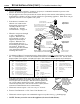
STOVE INSTALLATION (CONT.) - For Qualified Installers Only! PAGE 7 Heater Placement Requirements ¥ ¥ ? ¥ Heater must be installed on a level surface capable of supporting the heater and vent Due to the high temperature of the heater, it should be located out of traffic and away from furniture and draperies. Heater must be placed so no combustibles are within, or can swing within 36" of the front of the heater (e.g.
PAGE 8 STOVE INSTALLATION (CONT.) - For Qualified Installers Only! Vent Requirements ¥ When the vent passes through a wall, a wall thimble is required. When the vent passes through a ceiling, a support box or firestop is required. When the vent passes through the roof, a roof flashing and storm collar are required. Follow the instructions provided with the vent (from Duravent) for installing these items.
STOVE INSTALLATION (CONT.) - For Qualified Installers Only! Approved Vent Configurations Restrictor Position A vent restrictor is built into the appliance to adjust the flow rate of exhaust gases. This ensures proper flames for the wide variety of vent configurations. The restrictor consists of a butterfly valve below the starter section of pipe and an adjustment plate with index holes used to hold the valve in a fixed position.
¥ 10' Minimum System Height (with or without offsets) ¥ 33' Maximum System Height 0 feet Approved Venting Configurations for Vertical Terminations with (or without) Two 45° Elbows 33' (max) 30 feet ¥ 6' Maximum Offset ¥ The termination must fall within the shaded area shown in the chart. Use the indicated restrictor position. ¥ 6' (max) STOVE INSTALLATION (CONT.
STOVE INSTALLATION (CONT.) - For Qualified Installers Only! PAGE 11 Approved Venting Configurations with a Horizontal Termination If using a Snorkel Termination (14" or 36") add the snorkel height to the vertical height (snorkel terminations are used primarily for basement installations). ¥ The termination must fall within the shaded area shown in the chart. Use the indicated restrictor position.
PAGE 12 STOVE INSTALLATION (CONT.) - For Qualified Installers Only! Approved Configurations with a Vertical Termination and Two 90° Elbows 35' (max) 15 feet 16'(max) 10 feet 5 feet 0 feet ¥ The termination must fall within the shaded area shown in the chart. Use the indicated restrictor position.
STOVE INSTALLATION (CONT.) - For Qualified Installers Only! PAGE 13 Horizontal Vent Termination Requirements (see the illustration below) A B C D E F G H I J K L Minimum 9" (225 mm) clearance from any door or window Roof Minimum 12" (300 mm) above any grade, veranda, porch, deck or balcony Surface Minimum 12" (300 mm) from outside corner walls Minimum 12" (300 mm) from inside corner walls 11Ó Min. Roof 6Ó Min.
PAGE 14 INSERT INSTALLATION - For Qualified Installers Only! Installation Preparation ! Failure to follow all of the requirements may result in property damage, bodily injury, or even death. ! This appliance must be installed in accordance with all local codes, if any; if not, follow ANSI Z223.1 and NFPA 54(88). ! In Manufactured or Mobile Homes must confirm with: In USA, Manufactured Home Construction and Safety Standard, Title 24 CFR, Part 3280; In Canada, CSA Z240.
INSERT INSTALLATION (CONT.) - For Qualified Installers Only! PAGE 15 Re-Routing the Power Cord to the Front (continued) 2 Carefully pull on the power cord until the molex connector is exposed. Disconnect the molex connector. Molex Connectors Power Cord Wires Leading from the Heater 3 Pry out one of the button plugs on either side of the insert (see the illustration below). 4 Open the control cover and locate the wires leading from the power cord molex connector (green, white, and black wires).
PAGE 16 INSERT INSTALLATION (CONT.) - For Qualified Installers Only! Insert Placement Requirements Min. 29-3/4" WIde (includes 6" for gas line installation) The insert must be in place with the gas line and vent attached prior to installing the panels. Min. 22-1/8" Tall (includes 2" for vent installation) The Insert Must be Placed 13" into the Fireplace. Use the leveling bolts for fireplaces with recessed floors (included with the surround panels).
INSERT INSTALLATION (CONT.) - For Qualified Installers Only! PAGE 17 Gas Line Install ! ! ¥ The gas line must be installed in accordance with all local codes, if any; if not, follow ANSI Z223.1 and the requirements listed below. The heater and gas control valve must be disconnected from the gas supply piping during any pressure testing of that system at test pressures in excess of 1/2 psig. For pressures under 1/2 psig, isolate the gas supply piping by closing the manual shutoff valve.
PAGE 18 INSERT INSTALLATION (CONT.) - For Qualified Installers Only! Vent Requirements ! The gas appliance and vent system must be vented directly to the outside of the building, and never be attached to a chimney serving a separate solid fuel or gas-burning appliance. Each direct vent gas appliance must use it's own separate vent system. ! Make sure the exhaust pipe (the inner pipe) on the heater connects to the exhaust portion of the cap (the inner pipe).
INSERT INSTALLATION (CONT.) - For Qualified Installers Only! Approved Vent Configurations Restrictor Position A vent restrictor is built into the appliance to adjust the flow rate of exhaust gases. This ensures proper flames for the wide variety of vent configurations. The restrictor consists of a butterfly valve below the starter section of pipe and an adjustment plate with index holes used to hold the valve in a fixed position. Use the illustrations below to determine the correct restrictor position.
PAGE 20 ! FINALIZING THE INSTALLATION - For Qualified Installers Only! Turn the gas control valve to "OFF" prior to conducting any service. Unscrew and remove the door handle. 1 Swing the door until it is open 90¡ Lift the door up and away from the heater. Remove the door. NOTE: When re-installing, make sure the handle points away from the glass when finished. 2 Install the logs, twigs, and embers. Burner Pan Log Installation These clips keep the rear log from tilting backwards.
FINALIZING THE INSTALLATION (CONT.) - For Qualified Installers Only! Replace the door (follow the step # 1 in reverse order). To adjust the pilot flame, remove the cover screw (and The pilot flame should impinge the top 3/8Ó (10 mm) Turn on gas to the gasket) and turn the needle valve. Clockwise lowers of the thermopile. If it does not, you may need to the flame while counter-clockwise raises it. heater. Leak test all turn the pilot up. gas joints prior to Thermopile starting the appliance.
PAGE 22 OPERATING YOUR HEATER Before You Begin ! Read this entire manual before you use your new heater (especially the section "Safety Precautions" on pages 2 & 3). Failure to follow the instructions may result in property damage, bodily injury, or even death. Location of Controls - See explanation below ON/OFF Switch The on/off switch is located on the right side of the control cover. ON OF The Pilot Flame can be found below the back log on the left side.
OPERATING YOUR HEATER (CONTINUED) Starting The Pilot Flame a PI When lighting or re-lighting the pilot, the door must be removed (see page 20) Remove the door (see page 20 for details). b Push the gas control knob in slightly and turn it to the "OFF" position. The knob will not turn from "ON" to "OFF" unless the knob is depressed slightly. Wait five minutes to let any gas that may have accumulated inside the firebox escape.
PAGE 24 OPERATING YOUR HEATER (CONTINUED) Starting the Heater for the First Time ¥ Paint Curing insures a durable finish. Start the heater and burn on low for 20 minutes. Turn off and let cool. Repeat twice to fully cure the paint. + Fumes and smoke from the paint curing and oil burning off the steel may occur the first time you start your heater. This is normal. We recommend you open windows to vent the room. + Condensation may appear on the glass each time you start the heater - this is normal.
OPERATING YOUR HEATER (CONTINUED) PAGE 25 Adjusting the Blower Speed + The blower helps transfer the heat from the heater into the room. It will not turn on until the heater is up to temperature (approximately 10 minutes after starting). See the illustration below for instructions on adjusting the blower speed. Blower Knob OFF HI LO BLOWER PILOT IGNITER Turn the knob all the way counter-clockwise to turn the blower off. One click clockwise turns the blower to high speed.
PAGE 26 MAINTAINING YOUR HEATER Cleaning Your Heater ! The optional brass door may be cleaned with a non-abrasive polish (such as Flitz). The brass trim is anodized and should not be polished. Yearly Service Procedure ! Failure to inspect and maintain the heater may lead to improper combustion and a potentially dangerous situation. We recommend the following procedures be done by a qualified technician. 1 Check the pilot flame.
TROUBLESHOOTING Problem: Pilot Will Not Flame Possible Cause: PAGE 27 Don't Call for Service Until You: A gas shut off valve is turned off Check all gas shut off valves The gas control knob isn't turned to "PILOT" See "Starting the Pilot Flame" Pg 23 The valve control knob isn't pushed in See "Starting the Pilot Flame" Pg 23 The igniter wasn't pressed repeatedly See "Starting the Pilot Flame" Pg 23 The pilot flame has gone out See "Starting the Pilot Flame" Pg 23 The gas control valve is turne
PAGE 28 TROUBLESHOOTING (CONTINUED) How this Heater Works ! This heater was designed with safety as the primary concern. Many of the components inside this heater are for safety purposes. Therefore, only certified gas service technicians should service this heater. What Turns the Main Burners On and Off This electricity is used to operate the main burners. FF O H LO I O VENT N When heated, the thermopile generates electricity (a very small amount, measured in "Millivolts").
TROUBLESHOOTING (CONTINUED) PAGE 29 Why Nothing Should Be Placed Against the Heater Your heater has a grill on the sides, bottom, and top that must not be blocked. These grills are used to draw room air over the hottest parts of the heater and distribute the warmed air into the room. If they are blocked, the heater will not heat as well and may become too hot internally.
PAGE 30 WARRANTY To register your TRAVIS INDUSTRIES, INC. 7 Year Warranty, complete the enclosed warranty card and mail it within ten (10) days of the appliance purchase date to: TRAVIS INDUSTRIES, INC., 10850 117th Place N.E., Kirkland, Washington 98033. TRAVIS INDUSTRIES, INC. warrants this gas appliance (appliance is defined as the equipment manufactured by Travis Industries, Inc.
LISTING INFORMATION The safety label can be found on the back of the heater. A copy is shown below. Tested & Listed by 700 DV Beaverton, OR. USA TM Report No. 028-S-15-5 Listed Gas-Fired Direct Vent Wall Furnace and Fireplace Insert Tested and certified by OMNI-Test, Inc. to the following standards: USA: ANSI Z21.44-1992 Gas-Fired Gravity and Fan type Direct-Vent Wall Furnace, and applicable sections of Z21.11.1-1991 Gas-Fired Vented Room Heaters. CANADA: CAN 1-2.
PAGE 32 OPTIONAL EQUIPMENT Stove Leg Installation (Brass # 99200500, Cast Black # 99200800, Black Steel # 99200100) Raise the stove 8" (use lumber or other sturdy device). Attach each leg following the instructions below. Attach each leg to the stove by inserting a bolt and washer through the hole or slot in the leg and into the threaded hole on the stove. 9/16" Socket Wrench These rubber-tipped bolts are for leveling the stove. Make sure they contact the floor.
OPTIONAL EQUIPMENT (CONTINUED) PAGE 33 Surround Panel Installation + The surround panels come in the sizes listed below 2 3 HEIGHT WIDTH PART # 8" 10" 12" 28" 30" 32" 40" 44" 48" 99300259 99300260 99300261 The insert must be in place with the gas line and vent attached prior to installing the panels. The rear edge of the insert must be 13" behind the facing of the fireplace for the panels to fit correctly. Run the power cord to either side of the insert several inches in front of the facing.
PAGE 34 OPTIONAL EQUIPMENT (CONTINUED) Thermostat (Part # 99300650) ! 1 Do not connect 120 VAC to the gas control valve or wiring of this unit. Route the thermostat wire through the rear panel (run it through one of the ventilation holes) and attach to the on/off switch (see the illustration below). Route the wire under the burner pan forward, underneath this clip (this prevents it from touching the bottom of the burner pan. b a c Remove the green jumper wire.
OPTIONAL EQUIPMENT (CONTINUED) PAGE 35 Remote Thermostat ! Do not connect 110-120 VAC to the gas control valve or wiring system of this unit. ¥ Follow the instructions included with the remote thermostat for installation. IMPORTANT OPERATIONAL NOTE FOR REMOTE THERMOSTAT USE: Included with the remote thermostat is a set of instructions that should be given to the homeowner.
PAGE 36 3 OPTIONAL EQUIPMENT (CONTINUED) Remove the burner pan from the burner pan box following the instructions below. a Remove the two screws holding the burner box front in place. 1/4" Nutdriver Remove the burner box front. b Rotate the burner pan upwards. c Slide the burner pan to the left until the fixed shutter disengages from the orifice. Place the burner pan aside.
OPTIONAL EQUIPMENT (CONTINUED) 4 PAGE 37 Follow the directions below to remove the natural gas orifice. Apply thread sealant to the LP orifice (#50 - it has "50" stamped on it) and tighten in place with a 1/2" open end wrench. Replace the spring. Slide the adjustable shutter back in place. a c b Push the adjustable shutter to the left, off the orifice (be careful not to bend the shutter linkage). Slide the adjustable shutter down, away from the orifice.
PAGE 38 NOTE: These holes strip easily. Use a hand screwdriver and tighten each screw evenly. I H LO Align the regulator gasket so it is flat and the two tabs fit through the two holes on the gasket. These screws hold the regulator in place. NOTE: use the new screws included with the regulator. VENT 8 9 I H LO 7 Re-attach the burner pan and burner box front to the burner pan box following the instructions in step 3 in reverse order.
ADDENDUM PAGE 39 ADDENDUM #1 Altitude Considerations This heater has been tested at altitudes ranging from sea level to 8,000 feet (2,400 M). In this testing we have found that the fireplace, with its standard orifice, burns correctly with just an air shutter adjustment. For information on adjusting the air shutter see page 21 of this manual. ! Failure to adjust the air shutter properly may lead to improper combustion which can create a safety hazard.
PAGE 40 INDEX 151002 Adjusting the Blower Speed ......................................... 25 Lifting Flames ............................................................... 21 Adjusting the Flame Height .......................................... 24 Listing Label (Safety Label) .......................................... 31 AFUE ........................................................................... 5 Log Installation ............................................................