REN-CBW & EBC-05B1 Renity CBS Gateway 5.65” E-ink Bedside Card Quick Reference Guide 3rd Ed – 07 December 2020 Copyright Notice Copyright 2020 Avalue Technology Inc., ALL RIGHTS RESERVED. Part No.
REN-CBW & EBC-05B1 FCC Statement FEDERAL COMMUNICATIONS COMMISSION INTERFERENCE STATEMENT This equipment has been tested and found to comply with the limits for a Class B digital device, pursuant to part 15 of the FCC Rules. These limits are designed to provide reasonable protection against harmful interference in a residential installation.
Quick Reference Guide with antenna installation instructions and transmitter operating conditions for satisfying RF exposure compliance. A Message to the Customer Avalue Customer Services Each and every Avalue’s product is built to the most exacting specifications to ensure reliable performance in the harsh and demanding conditions typical of industrial environments.
REN-CBW & EBC-05B1 Content 1. Getting Started ........................................................................................................ 6 1.1 Safety Precautions .................................................................................................... 6 1.2 Packing List ............................................................................................................... 6 1.3 System Specifications ..........................................................................
Quick Reference Guide 4.3.4 Patient Management- Delete Patient Info (From Edit) .......................................................... 42 4.3.5 E Ink Card Screen Setting ..................................................................................................... 43 4.4 Patient Needs Management .................................................................................... 46 4.4.1 Patient Needs Management- E Ink Card Operating Instructions ..........................................
REN-CBW & EBC-05B1 1. Getting Started 1.1 Safety Precautions Warning! Always completely disconnect the power cord from your chassis whenever you work with the hardware. Do not make connections while the power is on. Sensitive electronic components can be damaged by sudden power surges. Only experienced electronics personnel should open the PC chassis. Caution! Always ground yourself to remove any static charge before touching the CPU card.
Quick Reference Guide 1.3 System Specifications REN-CBW System Mother Board REN-CBW Mother Board MCU ESP32-WROOM-32U/MDBT50Q-U1M Frequency 32.768KHz Wireless 802.11 b/g/n Bluetooth BT Bluetooth v4.2 / Bluetooth 5 Button ġ Front side external I/O 1 x button Mechanical & Environmental ġ Power Requirement DC +5V with Micro USB connector Power Type 5V DC Dimension 110.67 x 60.67 x 21.
REN-CBW & EBC-05B1 EBC-05B1 Component Mother Board EBC-05B1 MCU MDBT50Q – U1MV2 (nRF52840) Memory 1MB flash / 256KB RAM Power Supply Operating with 4 x AAAA batteries Wireless/BT BT 5.0 (WiFi + uP Module) Panel ġ LCD Panel 5.
Quick Reference Guide Note: Specifications are subject to change without notice.
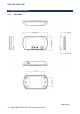
REN-CBW & EBC-05B1 1.4 System Dimensions 1.4.
Quick Reference Guide 1.4.
REN-CBW & EBC-05B1 2. Hardware Configuration Note: If you need more information, please visit our website: http://www.avalue.com.
Quick Reference Guide 2.1 REN-CBW & EBC-05B1 Overview 2.1.
REN-CBW & EBC-05B1 2.1.
Quick Reference Guide 2.2 REN-CBW Jumper and Connector List Jumpers Label Function Note JSPI_WP1 Write protection 3 x 1 header, pitch 2.00mm JBOOT1 Boot selector 2 x 1 header, pitch 2.00mm Label Function Note JSPI1 SPI connector 4 x 2 header, pitch 2.00mm SW1 Reset button SW2 Buzzer button JSWD1 SWD connector 4 x 1 header, pitch 2.00mm JUART1 UART Debug ESP32 connector 4 x 1 header, pitch 2.00mm JUART2 UART Debug M50Q connector 4 x 1 header, pitch 2.
REN-CBW & EBC-05B1 2.3 REN-CBW Jumpers & Connectors settings 2.3.1 Write protection (JSPI_WP1) LOW* HIGH * Default 2.3.
Quick Reference Guide 2.3.3 SPI connector (JSPI1) Signal 2.3.4 PIN PIN Signal +3.3VSB 1 2 GND SPI_CS_RST# 3 4 SPI_CLK SPI_IO1 5 6 SPI_IO0 SPI_IO3_HOLD# 7 8 SPI_IO2_WP# SWD connector (JSWD1) Signal PIN +3.
REN-CBW & EBC-05B1 2.3.5 2.3.6 18 UART Debug ESP32 connector (JUART1) Signal PIN +3.3VSB 1 ESP32_UART_TX 2 +3.3VSB 3 ESP32_UART_RX 4 Signal PIN +3.3VSB 1 M50Q_UART_RX 2 +3.
Quick Reference Guide 2.3.7 2.3.
REN-CBW & EBC-05B1 2.4 EBC-05B1 Connector List Connectors Label Function SW1 Reset button BB_JFPCA_1 FPCA connector 10 x 1 wafer, pitch 0.50mm JFPC1 FPC connector 1 24 x 1 wafer, pitch 0.50mm JFPC2 FPC connector 2 24 x 1 wafer, pitch 0.50mm JSWD1 SWD UART Debug connector 6 x 1 header, pitch 2.00mm JSPI1 SPI connector 4 x 2 header, pitch 2.
Quick Reference Guide 2.5 EBC-05B1 Connectors settings 2.5.1 SPI connector (JSPI1) Signal 2.5.2 PIN PIN Signal SPI0_IO2_WP# 8 7 SPI0_IO3_HOLD# SPI0_IO0 6 5 SPI0_IO1 SPI0_CLK 4 3 SPI0_CS# GND 2 1 +2.8VSB SWD UART Debug connector (JSWD1) Signal PIN DUART_RX 6 DUART_TX 5 GND 4 SWDCLK 3 SWDIO 2 +3.
REN-CBW & EBC-05B1 2.5.3 22 FPCA connector (BB_JFPCA_1) REN-CBW & EBC-05B1 Quick Reference Guide Signal PIN GND 1 BUTN3 2 BUTN2 3 BUTN1 4 BUTN0 5 LED3_B# 6 LED2_G# 7 LED1_R# 8 GND 9 +2.
Quick Reference Guide 2.5.4 FPC connector 1 (JFPC1) Signal PIN SPI1_CS2# 1 EPD_GDR 2 EPD_RESET 3 VGL 4 VGH 5 EPD_TSCL 6 EPD_TSDA 7 I2C1_SCL 8 EPD_BUSY 9 EPD_RESET# 10 SPI1_DCX 11 SPI1_CS1# 12 SPI1_CLK 13 SPI1_MOSI 14 +2.8VSB 15 +2.
REN-CBW & EBC-05B1 2.5.5 24 FPC connector 2 (JFPC2) REN-CBW & EBC-05B1 Quick Reference Guide Signal PIN GND 10 BTN3_R 9 LED1_B# 8 LED2_B# 7 BTN0_R 6 LED3B# 5 LED2G# 4 LED1R# 3 GND 2 +2.
Quick Reference Guide 3.
REN-CBW & EBC-05B1 3.1 Become Familiar Before you set up, take a moment to become familiar with the locations and purposes of the controls, drives, connections and ports, which are illustrated in the figures below. 1. Power Indicator 2. WiFi Indicator 3. Bluetooth Indicator ˏġ REN-CBW There are 3 buttons on the right to allow patients call for assistance which will correspond to the corresponding icons on the display. LED Behavior: 1. LED lights will flash 3 times when EBC-05B1 is powered up.
Quick Reference Guide 3.2 Setup Arrangement 1. Setup WIFI AP. 2. Setup Mini Server (Box PC) Box PC LAN port 1 must be connected to WIFI AP’s LAN port. 3. Login with box pc to web-based management platform using the correct account and passwords. Website: http://192.168.1.
REN-CBW & EBC-05B1 3.3 Installing REN-CBW Gateway Step 1. Device included 1 x REN-CB, 1 x USB adapter and 1 x Micro USB to USB cable. Step 2. Before installation, rotate counterclockwise the REN-CB cover to remove it. Step 3. Each REN-CB has a code number, located in the body back shell. Step 4. Channels for cable ties design allow ceiling/wall/adhesive tape installation. Step 5. Rotate clockwise to attach the unit and plug in USB power cable; the unit will startup automatically. Adhesive Tape Note: 1.
Quick Reference Guide 3.4 Installing Batteries to EBC-05B1 Patient Information Display Step1. Remove the battery cover. Step2. Press the battery spring, when removing batteries or replacing new one. Step3. Re-assemble your system back through previous steps to complete the installation.
REN-CBW & EBC-05B1 4.
Quick Reference Guide 4.1 Operation interface description 4.1.
REN-CBW & EBC-05B1 4.2 Settings 4.2.1 Basic Operation Instructions- Adding Beds This management system takes hospital bed equipment as basic structure.
Quick Reference Guide Click Setup from left main menu to enter Bed sub-menu, then click the Add icon on lower right corner. After filling in bed and patient information, clickȾAddȿto complete the process.
REN-CBW & EBC-05B1 4.2.2 Edit Bed Status Click the edit icon on the right side of the profile list. Modify bed and E Ink Card Setting. Click "Update" to complete the modification of bed information.
Quick Reference Guide 4.2.3 Deleting Beds Click the delete icon on the right side of the profile list. Click "OK" to delete the bed.
REN-CBW & EBC-05B1 4.2.4 E Ink Card Setting 4.2.
Quick Reference Guide 4.2.
REN-CBW & EBC-05B1 4.3 Patient Management 4.3.1 Patient Management- Add Patient Info Click on the main menu on the left, and the patient screen will show on the patient data by default. After filling in the patient information completely, click "Update" to complete the process.
Quick Reference Guide 4.3.2 Patient Management- Add Patient Info Click to edit icon to adjust patient related information.
REN-CBW & EBC-05B1 4.3.3 Patient Management- Delete Patient Info (Directly) Click Push icon. Click "OKȾ to complete the patient profile push.
Quick Reference Guide Click Delete icon.
REN-CBW & EBC-05B1 4.3.4 Patient Management- Delete Patient Info (From Edit) Click Edit icon. Click Delete icon 42 at the bottom right to delete the patient info.
Quick Reference Guide 4.3.5 E Ink Card Screen Setting For different patient needs and scenarios, sometimes more than 2 sets of E Ink Cards are needed and different information screens are provided. This unit provides flexible configuration settings focusing on patients. PS. This item is linked to the bed management of this system. Click on the main menu on the left, and the patient screen will show on the patient data by default. Click E Ink Card Setting icon.
REN-CBW & EBC-05B1 Click on the main menu on the left, and the patient screen will show on the patient data by default. Click Push icon 44 to complete the patient profile push.
Quick Reference Guide Click on the main menu on the left, and click E Ink Card Setting icon on the right. Click the new icon at the bottom right.
REN-CBW & EBC-05B1 4.4 Patient Needs Management 4.4.1 Patient Needs Management- E Ink Card Operating Instructions 4.4.2 Patient Needs Management- System Data Management Report system requirements after pressing and record the time message was sent.
Quick Reference Guide 4.4.3 Button Description Click the bell icon on upper right corner to enter notification center to pay attention to patient needs in time.
REN-CBW & EBC-05B1 4.5 Device Status Management 4.5.1 E Ink Card Status Management This unit only provides browsing of E Ink Card device status. (Battery Capacity, signal status and whether the bed is occupied.) 4.5.2 CBS Status Management E INK Card > Btn Set. This unit provides the signal status of CBS device.
Quick Reference Guide 4.6 Log in / Log out 4.6.1 Login Account Enter and fill in the administrator account and password. (Website: http://192.168.1.227/login) Move the mouse to the upper right corner of the screen, logout instruction appears on top of the account name.