ASM-BYT Fanless Intel® Celeron® SoC Ultra Slim PC Quick Reference Guide 1st Ed – 28 August 2014 Copyright Notice Copyright 2014 Avalue Technology Inc., ALL RIGHTS RESERVED. Part No.
ASM-BYT FCC Statement THIS DEVICE COMPLIES WITH PART 15 FCC RULES. OPERATION IS SUBJECT TO THE FOLLOWING TWO CONDITIONS: (1) THIS DEVICE MAY NOT CAUSE HARMFUL INTERFERENCE. (2) THIS DEVICE MUST ACCEPT ANY INTERFERENCE RECEIVED INCLUDING INTERFERENCE THAT MAY CAUSE UNDESIRED OPERATION. THIS EQUIPMENT HAS BEEN TESTED AND FOUND TO COMPLY WITH THE LIMITS FOR A CLASS "A" DIGITAL DEVICE, PURSUANT TO PART 15 OF THE FCC RULES.
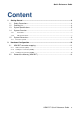
Quick Reference Guide Content 1. Getting Started ............................................................................................................ 4 1.1 1.2 1.3 1.4 1.4.1 Front View ................................................................................................................................ 7 1.4.2 Side & Rear View..................................................................................................................... 7 1.5 1.5.1 2. Safety Precautions ......
ASM-BYT 1. Getting Started 1.1 Safety Precautions Warning! Always completely disconnect the power cord from your chassis whenever you work with the hardware. Do not make connections while the power is on. Sensitive electronic components can be damaged by sudden power surges. Only experienced electronics personnel should open the PC chassis. Caution! Always ground yourself to remove any static charge before touching the CPU card. Modern electronic devices are very sensitive to static electric charges.
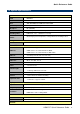
Quick Reference Guide 1.3 System Specifications System Board EBM-BYT CPU Intel® Celeron® Processor J1900 Family BIOS AMI uEFI BIOS, 64/128Mbit SPI Flash ROM System Chipset Valleyview D SoC Integrated I/O Chipset EC (IT8528E) System Memory One 204-pin SODIMM Socket Up to 8GB DDR3L 1333 SDRAM Watchdog Timer H/W Reset, 1sec. ~ 65535sec./1sec.
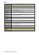
ASM-BYT Chipset 2 x Intel® I211AT Gigabit Ethernet Controller Ethernet Interface 10/100/1000 Base-Tx Gigabit Ethernet Compatible +12 ~ 26Vdc (Lockable DC Jack) Single Power ATX Support S0, S3, S4, S5 ACPI 3.
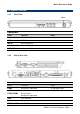
Quick Reference Guide 1.4 System Overview 1.4.1 Front View Power Connectors Label Function POWER Power on button USB USB 2.0 connector MIC IN Mic-in audio jack LINE IN Line-in audio jack LINE OUT Line-out audio jack 1.4.
ASM-BYT Optional PS/2 PWR System power indicator USB USB 2.0 connector x 1 USB 3.
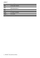
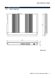
Quick Reference Guide 1.5 System Dimensions 1.5.
ASM-BYT 2. Hardware Configuration For advanced information, please refer to: 1- EBM-BYT User’s Manual Note: If you need more information, please visit our website: http://www.avalue.com.
Quick Reference Guide 2.1 ASM-BYT connector mapping 2.1.1 VGA connector (VGA) PIN Signal PIN Signal PIN Signal 1 R 6 GND 11 NC 2 G 7 GND 12 DATA 3 B 8 GND 13 HSYNC 4 NC 9 +5V 14 VSYNC 5 GND 10 GND 15 CLK 2.1.2 Serial port 1 connector (COM1) Signal PIN PIN Signal NDCDA#_485TXN 1 6 NDSRA# NRXDA_485TXP 2 7 NRTSA# NTXDA_485RXP 3 8 NCTSA# NDTRA#_485RXN 4 9 NRIA# GND 5 10 NC Note: COM1 can be set as RS-422/485 vis BIOS.
ASM-BYT 2.1.3 Serial port 2 connector (COM2) Signal PIN PIN Signal NDCDA#_485TXN 1 6 NDSRA# NRXDA_485TXP 2 7 NRTSA# NTXDA_485RXP 3 8 NCTSA# NDTRA#_485RXN 4 9 NRIA# GND 5 10 NC Note: COM2 can be set as RS-422-485 vis DIP Switch.
Quick Reference Guide 2.2 Remove the Memory (ASM-BYT) Step1. Remove 3 screws from the rear side before removing back cover. Step2. Remove 3 screws from the bottom of your system. Step3. Remove the top chassis.
ASM-BYT Step4.1 Remove the memory module. Step4.2 Re-assemble your system back through previous steps to complete the installation.