BFC-10R1 10.1" RISC Bezel Free Panel PC with FreeScale IMX51 Quick Reference Guide 1st Ed –15 March 2013 Copyright Notice Copyright 2013 Avalue Technology Inc., ALL RIGHTS RESERVED. Part No.
BFC-10R1 FCC Statement THIS DEVICE COMPLIES WITH PART 15 FCC RULES. OPERATION IS SUBJECT TO THE FOLLOWING TWO CONDITIONS: (1) THIS DEVICE MAY NOT CAUSE HARMFUL INTERFERENCE. (2) THIS DEVICE MUST ACCEPT ANY INTERFERENCE RECEIVED INCLUDING INTERFERENCE THAT MAY CAUSE UNDESIRED OPERATION. THIS EQUIPMENT HAS BEEN TESTED AND FOUND TO COMPLY WITH THE LIMITS FOR A CLASS "A" DIGITAL DEVICE, PURSUANT TO PART 15 OF THE FCC RULES.
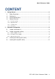
Quick Reference Guide CONTENT 1. Getting Started ............................................................................................................ 4 1.1 1.2 1.3 1.4 2. Safety Precautions ................................................................................................ 4 Packing List ........................................................................................................... 4 System Specifications ..................................................................
BFC-10R1 1. Getting Started 1.1 Safety Precautions Warning! Always completely disconnect the power cord from your chassis whenever you work with the hardware. Do not make connections while the power is on. Sensitive electronic components can be damaged by sudden power surges. Only experienced electronics personnel should open the PC chassis. Caution! Always ground yourself to remove any static charge before touching the CPU card. Modern electronic devices are very sensitive to static electric charges.
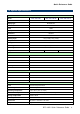
Quick Reference Guide 1.3 System Specifications Panel Model BFC-10R1-M51 BFC-10R1-M51W BFC-10R1-M51P 10.1” LCD size WSVGA TFT Display type 1024 x 600 Resolution 262K Color Pixel pitch 0.1905mm(H) x 0.
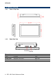
BFC-10R1 1.4 System Overview 1.4.1 Front & Top View 1.4.
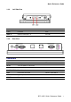
Quick Reference Guide 1.4.3 Left Side View Connectors Label Function Note USB1~2 USB 2.0 connector 1~2 Left side 1.4.
BFC-10R1 2. Hardware Configuration Jumper and Connector Setting, Driver and BIOS Installing For advanced information, please refer to: 1- RSC-IMX51 Installation Guide or User’s Manual 2- EPM-POE and AUX-MPCIE (Optional) Installation Guide. Note: If you need more information, please visit our website: http://www.avalue.com.
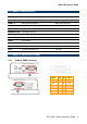
Quick Reference Guide 2.1 Jumper & connector list Connectors Label Function Note COM1~2 Serial port connector1~2 DB-9 male connector DC-IN +12V DC power-in connector LAN RJ-45 Fast Ethernet connector MODE SWITCH Boot Mode selector POE RJ-45 POE connector Power S/W System power switch RESET Reset button SD Card Slot SD/SDHC card socket Right side Mini USB USB client connector Right side USB USB 2.0 connector 1&2 Left side For BFC-10R1-M51P 2.2 Jumper & connector settings 2.2.
BFC-10R1 2.2.2 Boot Mode selector (SW2) Boot from onboard SD Boot from SD socket Signal PIN PIN BMOD1 1 5 BMOD0 2 6 BT_SRC[1] 3 7 BT_SRC[0] 4 8 Signal +V2D775_BOOT +V1D8_DIG1 USB OTG mode (Reflash onboard SD only) Please note: DIP Switch setting: 0=Off, 1=On When Position4 is switched On, the system is forced to power On as soon as power is applied. Switch to Off mode for normal operation. 2.2.
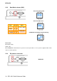
Quick Reference Guide 2.3 Installing PCIE device (BFC-10R1) Step1. Remove the 8 screws to disassemble your system back cover. Step2.
BFC-10R1 2.4 Installing SD Card (BFC-10R1) Step1. Put SD Card into the SD Card Slot.