EBM-A50M 5.25" AMD eOntario Mini Module with AMD A50M Chipset + T40E Processor Quick Installation Guide 1st Ed – 24 October 2011 Copyright Notice Copyright 2011 Avalue Technology Inc., ALL RIGHTS RESERVED. Part No.
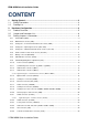
EBM-A50M Quick Installation Guide CONTENT 1. Getting Started ............................................................................................................ 3 1.1 Safety Precautions .................................................................................................... 3 1.2 Packing List ............................................................................................................... 3 2. Hardware Configuration ........................................................
Quick Installation Guide 1. Getting Started 1.1 Safety Precautions Warning! Always completely disconnect the power cord from your chassis whenever you work with the hardware. Do not make connections while the power is on. Sensitive electronic components can be damaged by sudden power surges. Only experienced electronics personnel should open the PC chassis. Caution! Always ground yourself to remove any static charge before touching the CPU card.
EBM-A50M Quick Installation Guide 2.
Quick Installation Guide 2.
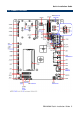
EBM-A50M Quick Installation Guide 2.2 Jumper and Connector List You can configure your board to match the needs of your application by setting jumpers. A jumper is the simplest kind of electric switch. It consists of two metal pins and a small metal clip (often protected by a plastic cover) that slides over the pins to connect them. To “close” a jumper you connect the pins with the clip. To “open” a jumper you remove the clip. Sometimes a jumper will have three pins, labeled 1, 2, and 3.
Quick Installation Guide Connectors Label BAT-WB CFCARD COM1 CPU_FAN DIMM JAUDIO JBKL1 JBKL2 JCIR JCOM2 JCOM3 JCOM4 JCOM5 JCOM6 JDIO JKEY JLED JLVDS1 JLVDS2 JLPC JSPI JTOUCH JUSB1 JUSB2 JUSB3 Function Battery connector Compact Flash card connector Serial Port 1 connector CPU fan connector 204-pin DDR3 SODIMM socket Audio connector LCD Inverter connector LCD Inverter connector CIR connector (Optional) Serial Port 2 connector Serial Port 3 connector Serial Port 4 connector Serial Port 5 connector Serial Port
EBM-A50M Quick Installation Guide S_PWR1 S_PWR2 SATA1 SATA2 SATA3 USB1 12V_PWR Serial ATA power connector 1 2 x 1 wafer, pitch 2.0mm Serial ATA power connector 2 2 x 1 wafer, pitch 2.0mm Serial ATA connector 1 Serial ATA connector 2 SATA-HDD connector (Optional) USB connector 0&1 12V Power Output (Max:1A) (Optional) 3 x 1 wafer, pitch 2.
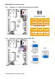
Quick Installation Guide 2.3 Setting Jumpers & Connectors 2.3.1 Clear CMOS (JBAT) Protect* Clear CMOS * Default 2.3.
EBM-A50M Quick Installation Guide 2.3.3 Serial port 1/ 2 - RS-232/ 422/ 485 mode selector (SW2) In Serial Port 1 mode RS-232 RS-422 RS-485 1 ON OFF OFF 2 OFF ON OFF 3 OFF OFF ON In Serial Port 2 mode 2.3.
Quick Installation Guide 2.3.5 Serial port 1/ 2 RS-232/ 422/ 485 mode selector (JP1/ JP2) RS-232* JP2 JP1 RS-422/ 485 * Default 2.3.
EBM-A50M Quick Installation Guide 2.3.7 2.3.8 Battery connector (BAT-WB) Signal PIN BAT 1 GND 2 LED indicator connector (JLED) Signal 12 EBM-A50M Quick Installation Guide PIN PIN Signal GND 1 2 +3.3V HD_LED# 3 4 +3.3V LAN1_ACT 5 6 3.3V_SB LAN2_ACT 7 8 3.
Quick Installation Guide 2.3.9 LCD backlight brightness adjustment (JVR) Mode1: VR type Mode 2: DC type* * Default Signal PIN PIN Signal +5V 1 2 DC VR 3 4 VR GND 5 6 PWM Note: DC: 0V ~5V Mode 3: Pulse-Width Modulated type Variation Resistor (Recommended: 4.7KΩ, >1/16W) Note: For inverters with adjustable Backlight function, it is possible to control the LCD brightness through the VR signal controlled by JBKL1. Please see the JBKL1 section for detailed circuitry information.
EBM-A50M Quick Installation Guide 2.3.10 2.3.
Quick Installation Guide 2.3.12 2.3.13 LCD Inverter connector (JBKL1) Signal PIN +5V 5 BRIGHT 4 BLK_ON 3 GND 2 +12V 1 Signal PIN GND 2 +12V 1 LCD Inverter connector (JBKL2) Note: For inverters with adjustable Backlight function, it is possible to control the LCD brightness through the VR signal controlled by JVR. Please see the JVR section for detailed circuitry information.
EBM-A50M Quick Installation Guide 2.3.13.1 Signal Description – LCD Inverter Connector (JBKL1/ JBKL2) Signal Signal Description BRIGHT Vadj = 0.75V ~ 4.25V (Recommended: 4.7KΩ, >1/16W) BKL_ON LCD backlight ON/OFF control signal 2.3.
Quick Installation Guide 2.3.
EBM-A50M Quick Installation Guide 2.3.16 2.3.
Quick Installation Guide 2.3.
EBM-A50M Quick Installation Guide 2.3.19 Serial port 3/ 4/ 5/ 6 connector (JCOM3/ JCOM4/ JCOM5/ JCOM6) JCOM3 JCOM4 JCOM5 JCOM3 JCOM6 Signal 2.3.
Quick Installation Guide 2.3.21 LVDS connector (JLVDS1) Signal PIN PIN +5V 2 1 +5V 4 3 2 Signal +3.3V +3.3V 2 I C_DAT 6 5 I C_CLK GND 8 7 GND Txout0 10 9 Txout1 Txout0# 12 11 Txout1# GND 14 13 GND Txout2 16 15 NC Txout2# 18 17 NC GND 20 19 GND NC 22 21 NC NC 24 23 NC GND 26 25 GND NC 28 27 NC NC 30 29 NC GND 32 31 GND Txclk 34 33 NC Txclk# 36 35 NC GND 38 37 GND +12V 40 39 +12V 2.3.21.
EBM-A50M Quick Installation Guide 2.3.22 LVDS connector (JLVDS2) Signal PIN PIN Signal +5V 2 1 +3.3V +5V 4 3 +3.
Quick Installation Guide 2.3.23 Touch panel connector (JTOUCH) Signal PIN UL 1 UR 2 PROBE 3 LR 4 LL 5 NOTE: Under 4W situation UL=X+, UR=Y+, LR=Y-, LL=X- 2.3.24 USB connector 2&3, 4&5, 6&7 (JUSB1/ JUSB2 / JUSB3) JUSB3 JUSB2 JUSB1 Signal PIN PIN Signal +5V 1 2 GND D- 3 4 GND D+ 5 6 D+ GND 7 8 D- GND 9 10 +5V Note: JUSB3-3.
EBM-A50M Quick Installation Guide 2.3.25 2.3.26 SPI connector (JSPI) Signal PIN PIN Signal +3.3V 1 2 GND CS# 3 4 CLK DI_R 5 6 DO HOLD 7 Signal PIN PIN Signal AD0 1 2 +3.