ECM-A50M 3.5” AMD eOntario Module Quick Installation Guide 2nd Ed – 3 March 2012 Part No.
ECM-A50M Quick Installation Guide FCC Statement THIS DEVICE COMPLIES WITH PART 15 FCC RULES. OPERATION IS SUBJECT TO THE FOLLOWING TWO CONDITIONS: (1) THIS DEVICE MAY NOT CAUSE HARMFUL INTERFERENCE. (2) THIS DEVICE MUST ACCEPT ANY INTERFERENCE RECEIVED INCLUDING INTERFERENCE THAT MAY CAUSE UNDESIRED OPERATION. THIS EQUIPMENT HAS BEEN TESTED AND FOUND TO COMPLY WITH THE LIMITS FOR A CLASS "A" DIGITAL DEVICE, PURSUANT TO PART 15 OF THE FCC RULES.
ECM-A50M Quick Installation Guide first. To receive the latest version of the user’s manual; please visit our Web site at: http://www.avalue.com.tw/ If you still cannot find the answer, gather all the information or questions that apply to your problem, and with the product close at hand, call your dealer. Our dealers are well trained and ready to give you the support you need to get the most from your Avalue’s products.
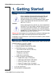
ECM-A50M Quick Installation Guide 1. Getting Started 1.1 Safety Precautions Warning! Always completely disconnect the power cord from your chassis whenever you work with the hardware. Do not make connections while the power is on. Sensitive electronic components can be damaged by sudden power surges. Only experienced electronics personnel should open the PC chassis. Caution! Always ground yourself to remove any static charge before touching the CPU card.
ECM-A50M Quick Installation Guide 2.
ECM-A50M Quick Installation Guide 2.
ECM-A50M Quick Installation Guide ECM-A50M Quick Installation Guide 7
ECM-A50M Quick Installation Guide 2.2 Jumper and Connector List You can configure your board to match the needs of your application by setting jumpers. A jumper is the simplest kind of electric switch. It consists of two metal pins and a small metal clip (often protected by a plastic cover) that slides over the pins to connect them. To “close” a jumper you connect the pins with the clip. To “open” a jumper you remove the clip. Sometimes a jumper will have three pins, labeled 1, 2, and 3.
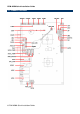
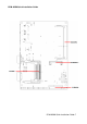
ECM-A50M Quick Installation Guide Connectors Label Function Note BAT-WB Battery connector 2 x 1 wafer, pitch 1.25 mm COM1 Serial port 1 connector D-sub 9-pin, male CFCARD CF card connector CPU_FAN1 CPU fan connector 4 x 1 wafer DCIN Power connector 2 x 2 wafer, pitch 4.2 mm FLED1 LED connector HDMI HDMI connector 19 pin J422/485 Serial port 1 in RS-422/485 mode 3 x 2 header, pitch 2.0 mm JAUDIO Audio connector 6 x 2 header, pitch 2.
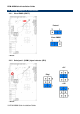
ECM-A50M Quick Installation Guide 2.3 Setting Jumpers & Connectors 2.3.1 Clear CMOS (JBAT1) Protect* Clear CMOS * Default 2.3.
ECM-A50M Quick Installation Guide 2.3.3 Serial port 2 (COM2) signal selector (JRI2) +5V Ring* +12V * Default 2.3.
ECM-A50M Quick Installation Guide 2.3.5 AT/ ATX power Input selector (JAT/ATX) AT* ATX * Default 2.3.
ECM-A50M Quick Installation Guide 2.3.6.1 Signal Description –AT/ATX mode & Input power type Input power type Power-ON Mode Description AT Mode (JAT/ATX) Use AT type power input, and set the board in AT mode. AT Type (DCIN) ATX Mode (JAT/ATX) Use AT type power input, and set the board in ATX mode. AT Mode (JAT/ATX) Use ATX type power input, and set the board in AT mode. ATX Type (PWR_SB) ATX Mode (JAT/ATX) Use ATX type power input, and set the board in ATX mode.
ECM-A50M Quick Installation Guide 2.3.7 ErP Power saving mode selector (JDEEPS5) DEEPS5=0* DEEPS5=1 Signal PIN DEEPS5_SEL 1 GND 2 * Default 2.3.7.1 ErP Power saving mode selector setting details Settings Description DEEPS5=0 System will not enter deep S5 state after AC power on, it remains in normal ACPI S5 state. DEEPS5=1 System will enter deep S5 state 6 sec after AC power on.
ECM-A50M Quick Installation Guide 2.3.8 Touch selector (JTSEL) 4/8W* 5W JTOUCH * Default 2.3.
ECM-A50M Quick Installation Guide 2.3.10 CPU fan connector (CPU_FAN) Signal PIN GND 1 +V12S 2 SIO_FANI 3 SIO_FANO 4 2.3.
ECM-A50M Quick Installation Guide 2.3.12 Audio connector (JAUDIO) Signal PIN PIN Signal GND 12 11 MIC1_JD LIN1_JD 10 9 FRONT_JD MIC1_L 8 7 MIC1_R LIN1_L 6 5 LIN1_R GND 4 3 GND FRONT_L 2 1 FRONT_R 2.3.13 LCD backlight brightness adjustment (JVR) Signal PIN GND 3 LVDS_BLKT_CTRL 2 +5V 1 Variation Resistor (Recommended: 4.
ECM-A50M Quick Installation Guide 2.3.14 LCD Inverter Connector (JBKL) Signal PIN +5V 5 BRIADJ 4 BKLEN 3 GND 2 +12V 1 Note: For inverters with adjustable Backlight function, it is possible to control the LCD brightness through the VR signal controlled by JVR. Please see the JVR section for detailed circuitry information. 2.3.14.1Signal Description – LCD Inverter Connector (JBKL) Signal Signal Description BRIADJ Vadj = 0.75V ~ 4.25V (Recommended: 4.
ECM-A50M Quick Installation Guide 2.3.15 Serial port 2 connector (JCOM2) Signal PIN PIN Signal DCD 1 2 RXD TXD 3 4 DTR 6 DSR GND RTS 7 8 CTS RI2 9 10 NC 2.3.
ECM-A50M Quick Installation Guide 2.3.
ECM-A50M Quick Installation Guide 2.3.18 2.3.19 Miscellaneous setting connector (JFP) Signal PIN PIN Signal GND 10 9 CASEOPEN# +3.3V 8 7 HD_LED# PWR_LED# 6 5 3.
ECM-A50M Quick Installation Guide 2.3.20 Low pin count interface connector (JLPC) Signal 2.3.21 PIN PIN Signal LPC_LDRQ# 14 13 +5V GND 12 11 +5V GND 10 9 LPC_SERIRQ CLK_JLPC 8 7 LPC_AD3 LPC_FRAME# 6 5 LPC_AD2 A_RST# 4 3 LPC_AD1 +3.3V 2 1 LPC_AD0 SPI connector (JSPI) 22 ECM-A50M Quick Installation Guide Signal PIN PIN Signal +3.
ECM-A50M Quick Installation Guide 2.3.
ECM-A50M Quick Installation Guide 2.3.23 USB connector 0 & 1/ 4 & 5/ 2 & 3 (JUSB1/2/3) JUSB1 JUSB2 JUSB3 Signal 2.3.