ECM-DX2 DX&P Vortex86DX2 3.5” Micro Module Quick Installation Guide 1st Ed – 25 December 2013 Part No.
ECM-DX2 Quick Installation Guide FCC Statement THIS DEVICE COMPLIES WITH PART 15 FCC RULES. OPERATION IS SUBJECT TO THE FOLLOWING TWO CONDITIONS: (1) THIS DEVICE MAY NOT CAUSE HARMFUL INTERFERENCE. (2) THIS DEVICE MUST ACCEPT ANY INTERFERENCE RECEIVED INCLUDING INTERFERENCE THAT MAY CAUSE UNDESIRED OPERATION. THIS EQUIPMENT HAS BEEN TESTED AND FOUND TO COMPLY WITH THE LIMITS FOR A CLASS "A" DIGITAL DEVICE, PURSUANT TO PART 15 OF THE FCC RULES.
ECM-DX2 Quick Installation Guide 1. Getting Started 1.1 Safety Precautions Warning! Always completely disconnect the power cord from your chassis whenever you work with the hardware. Do not make connections while the power is on. Sensitive electronic components can be damaged by sudden power surges. Only experienced electronics personnel should open the PC chassis. Caution! Always ground yourself to remove any static charge before touching the CPU card.
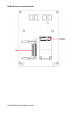
ECM-DX2 Quick Installation Guide 2.
ECM-DX2 Quick Installation Guide 2.
ECM-DX2 Quick Installation Guide 6 ECM-DX2 Quick Installation Guide
ECM-DX2 Quick Installation Guide 2.2 Jumper and Connector List You can configure your board to match the needs of your application by setting jumpers. A jumper is the simplest kind of electric switch. It consists of two metal pins and a small metal clip (often protected by a plastic cover) that slides over the pins to connect them. To “close” a jumper you connect the pins with the clip. To “open” a jumper you remove the clip. Sometimes a jumper will have three pins, labeled 1, 2, and 3.
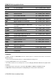
ECM-DX2 Quick Installation Guide SPWR1 SATA Power connector 2 x 1 wafer, pitch 2.00 mm PC-104 PC-104 connector 20 x 2 header, pitch 2.54mm PC-104 PC-104 connector 32 x 2 header, pitch 2.54mm JTG1 Reserved for Debug 3 x 2 header, pitch 2.00 mm AUD1 Audio connector 6 x 2 header, pitch 2.00 mm BKL1 LCD inverter connector 5 x 1 wafer, pitch 2.00 mm COM1 Serial port 1 connector D-sub 9-pin, male COM2/3/4 Serial port 2/3/4 connector 5 x 2 header, pitch 2.
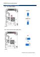
ECM-DX2 Quick Installation Guide 2.3 Setting Jumpers & Connectors 2.3.1 Clear CMOS (CMOS1) Normal* CMOS Clear * Default 2.3.
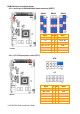
ECM-DX2 Quick Installation Guide 2.3.3 Serial port in RS232/422/485 mode connector (CSET1) RS232* Signal * Default RS422 RS485 PIN PIN Signal COM3_M1_EN 12 11 GND +5V 10 9 COM3_M0 SUS_LED# 8 7 COM3_M0_H COM2_M1_EN 6 5 GND +5V 4 3 COM2_M0 NRX2# 2 1 COM2_M0_H 2.3.
ECM-DX2 Quick Installation Guide 2.3.5 COM 2/4 pin 9 signal select (JRI2/4) +5V JRI2 JRI4 Ring* +12V * Default 2.3.
ECM-DX2 Quick Installation Guide 2.3.7 5VSB connector in ATX (PWR_SB1) Signal PIN PS_ON# 1 NA 2 +5V 3 Signal PIN GND 2 +3.3V 1 2.3.
ECM-DX2 Quick Installation Guide 2.3.9 Power connector (PWR1) Signal PIN PIN Signal GND 1 2 GND +12V 3 4 +12V 2.3.
ECM-DX2 Quick Installation Guide 2.3.11 LCD inverter connector (BKL1) Signal PIN +5V 5 BRIGHT 4 TTL_ENBLT 3 GND 2 +12V 1 2.3.
ECM-DX2 Quick Installation Guide 2.3.13 Audio connector (AUD1) Signal PIN PIN Signal LINEOUT_R 1 2 LINEOUT_L GND 3 4 GND LINE1-RIN 5 6 LINE1-LIN MIC-RIN 7 8 MIC-LIN FRONT-JD 9 10 LINE1_JD MIC1_JD 11 12 GND 2.3.13.
ECM-DX2 Quick Installation Guide 2.3.14 Serial port 2/3/4 connector (COM2/3/4) COM2 COM3 COM4 Signal PIN PIN Signal NDCD2/3/4# 1 2 NRX2/3/4# NTX2/3/4# 3 4 NDTR2/3/4# GND 5 6 NDSR2/3/4# NRTS2/3/4# 7 8 NCTS2/3/4# NRI2/3/4# 9 10 NC 2.3.
ECM-DX2 Quick Installation Guide 2.3.
ECM-DX2 Quick Installation Guide 2.3.17 On-board pin header for USB2.0 (USB1) Signal PIN PIN Signal +5V 1 2 GND USB0N 3 4 GND USB0P 5 6 USB1P GND 7 8 USB1N GND 9 10 +5V 2.3.18 On-board pin header for USB2.
ECM-DX2 Quick Installation Guide 2.3.19 Reserved for Debug (JTG1) Signal PIN PIN Signal +5V 1 2 GND TD0 3 4 TCK TDI 5 6 TMS 2.3.
ECM-DX2 Quick Installation Guide 2.3.21 LCD PWM Mode Selector (BPWM1) Signal PIN BRIGHT 1 PWM_D_BKLTCTRL 2 2.3.