ECM-LX800 Series 3.5” AMD LX800 @0.9W Micro Module Quick Installation Guide 3rd Ed – 09 October 2008 Part No.
ECM-LX800 Series Contents 1. Getting Started............................................................................................................3 1.1 Safety Precautions ................................................................................................3 1.2 Packing List ...........................................................................................................3 2. Hardware Configuration...................................................................................
Quick Installation Guide 1. Getting Started 1.1 Safety Precautions Warning! Always completely disconnect the power cord from your chassis whenever you work with the hardware. Do not make connections while the power is on. Sensitive electronic components can be damaged by sudden power surges. Only experienced electronics personnel should open the PC chassis. Caution! Always ground yourself to remove any static charge before touching the CPU card.
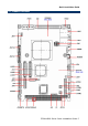
ECM-LX800 Series 2.
Quick Installation Guide 2.
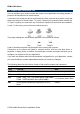
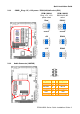
ECM-LX800 Series 2.2 Jumper and Connector List You can configure your board to match the needs of your application by setting jumpers. A jumper is the simplest kind of electric switch. It consists of two metal pins and a small metal clip (often protected by a plastic cover) that slides over the pins to connect them. To “close” a jumper you connect the pins with the clip. To “open” a jumper you remove the clip. Sometimes a jumper will have three pins, labeled 1, 2, and 3.
Quick Installation Guide Connectors Label Function Note COM1 Serial port 1 connector D-sub 9-pin, male CF Card CompactFlash card connector Type I/II x 1 IDE Primary IDE connector 22 x 2 header, pitch 2.0mm JAUDIO Audio connector 5 x 2 header, pitch 2.0mm JBKL LCD inverter connector 5 x 1 wafer, pitch 2.0mm JCDIN CD-ROM audio input connector 4 x 1 wafer, pitch 2.0mm JCOM2 JCOM3 JCOM4 Serial port 2 connector Serial port 3 connector Serial port 4 connector 5 x 2 header, pitch 2.
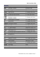
ECM-LX800 Series 2.3 Setting Jumpers & Connectors 2.3.1 Clear CMOS (JBAT) Protect* Clear CMOS * Default 2.3.
Quick Installation Guide 2.3.3 COM2-Ring, +5V, +12V power / RS232,422,485 select(JRI2 ) ECM-LX800A Ring, +5V, +12V power select ECM-LX800B RS232,422,485 select Ring* RS232* * Default * Default 2.3.
ECM-LX800 Series 2.3.5 CPU frequency & Memory frequency & AT/ATX select (SW1) LX800@0.
Quick Installation Guide 2.3.6 LCD inverter connector (JBKL) Signal PIN +12V 1 GND 2 ENBKL 3 VR 4 +5V 5 Note: For inverters with adjustable Backlight function, it is possible to control the LCD brightness through the VR signal controlled by JVR. Please see the JVR section for detailed circuitry information. 2.3.6.1 Signal Description – LCD Inverter Connector (JBKL) Signal Signal Description VR Vadj = 0.75V ~ 4.25V (Recommended: 4.
ECM-LX800 Series 2.3.7 2.3.
Quick Installation Guide 2.3.9 2.3.
ECM-LX800 Series 2.3.11 2.3.
Quick Installation Guide 2.3.
ECM-LX800 Series 2.3.14 LVDS Connector (JLVDS) Signal PIN PIN Signal +5V 2 1 +3.3V +5V 4 3 +3.3V I2C_DAT 6 5 I2C_CLK GND 8 7 GND Txout0 10 9 Txout1 Txout0# 12 11 Txout1# GND 14 13 GND Txout2 16 15 Txout3 Txout2# 18 17 Txout3# GND 20 19 GND NC 22 21 NC NC 24 23 NC GND 26 25 GND NC 28 27 NC NC 30 29 NC GND 32 31 GND Txclk 34 33 NC Txclk# 36 35 NC GND 38 37 GND +12V 40 39 +12V 2.3.14.
Quick Installation Guide 2.3.15 TFT Panel Connector (JTFT) Signal PIN PIN Signal +5V 2 1 +5V GND 4 3 GND +3.3V 6 5 +3.
ECM-LX800 Series 2.3.15.1 Signal Description – TFT Panel Connector (JTFT) Signal Description P [0:23] Flat panel data output for 18/24 bit TFT flat panels. Refer to table below for configurations for various panel types. The flat panel data and control outputs are all on-board controlled for secure power-on/off sequencing SHFCLK Shift Clock.
Quick Installation Guide 2.3.16 2.3.
ECM-LX800 Series 2.3.
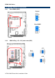
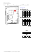
Quick Installation Guide 2.4 Audio / USB Daughter Board User’s Guide 2.4.1 Jumper and Connector Layout 2.4.2 Jumper and Connector List Jumpers Label Function Note JP6 Line out / Speaker out select (The speaker 1-3, 2-4 Speaker out out function is only available in combine 3-5, 4-6 Line out (Default) used of main board) Connectors Label Function Note CN1, CN2 USB 1.1/2.
ECM-LX800 Series 2.4.3 Setting Jumper and Connector Line out / Speaker out Select (JP6) 2.54mm USB 1.1/2.0 Connector 1 (JP1) Line Out* Signal PIN PIN Signal +5V 1 2 GND D1- 3 4 GND D1+ 5 6 D2+ GND 7 8 D2- GND 9 10 +5V Speaker Out Note: Wrong USB cable configuration with your USB devices might cause your USB devices damaged. 2.
Quick Installation Guide Avalue Customer Services Each and every Avalue’s product is built to the most exacting specifications to ensure reliable performance in the harsh and demanding conditions typical of industrial environments. Whether your new Avalue device is destined for the laboratory or the factory floor, you can be assured that your product will provide the reliability and ease of operation for which the name Avalue has come to be known. Your satisfaction is our primary concern.
ECM-LX800 Series 24 ECM-LX800 Series Quick Installation Guide