ECM-LX800D 3.5” AMD LX800 Micro Module Quick Installation Guide 1st Ed – 5 May 2010 Part No.
ECM-LX800D FCC Statement THIS DEVICE COMPLIES WITH PART 15 FCC RULES. OPERATION IS SUBJECT TO THE FOLLOWING TWO CONDITIONS: (1) THIS DEVICE MAY NOT CAUSE HARMFUL INTERFERENCE. (2) THIS DEVICE MUST ACCEPT ANY INTERFERENCE RECEIVED INCLUDING INTERFERENCE THAT MAY CAUSE UNDESIRED OPERATION. THIS EQUIPMENT HAS BEEN TESTED AND FOUND TO COMPLY WITH THE LIMITS FOR A CLASS "A" DIGITAL DEVICE, PURSUANT TO PART 15 OF THE FCC RULES.
Quick Installation Guide Contents 1. Getting Started............................................................................................................4 1.1 Safety Precautions ................................................................................................4 1.2 Packing List ...........................................................................................................4 2. Hardware Configuration...........................................................................
ECM-LX800D 1. Getting Started 1.1 Safety Precautions Warning! Always completely disconnect the power cord from your chassis whenever you work with the hardware. Do not make connections while the power is on. Sensitive electronic components can be damaged by sudden power surges. Only experienced electronics personnel should open the PC chassis. Caution! Always ground yourself to remove any static charge before touching the CPU card. Modern electronic devices are very sensitive to static electric charges.
Quick Installation Guide 2.
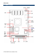
ECM-LX800D 2.
Quick Installation Guide 2.2 Jumper and Connector List You can configure your board to match the needs of your application by setting jumpers. A jumper is the simplest kind of electric switch. It consists of two metal pins and a small metal clip (often protected by a plastic cover) that slides over the pins to connect them. To “close” a jumper you connect the pins with the clip. To “open” a jumper you remove the clip. Sometimes a jumper will have three pins, labeled 1, 2, and 3.
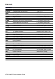
ECM-LX800D Connectors Label Function Note CFCARD CompactFlash card connector Type I/II x 1 COM1 Serial port 1 connector D-sub 9-pin, male IDE Primary IDE connector 22 x 2 header, pitch 2.0mm JAUDIO Audio connector 5 x 2 header, pitch 2.0mm JBKL LCD inverter connector 5 x 1 wafer, pitch 2.0mm JCOM2 Serial port 2 in RS-232 mode connector 5 x 2 header, pitch 2.0mm JDIO General purpose I/O connector 5 x 2 header, pitch 2.0mm JIR IrDA connector 5 x 1 header, pitch 2.
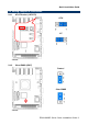
Quick Installation Guide 2.3 Setting Jumpers & Connectors 2.3.1 AT/ATX select (JAT/ATX) ATX* AT * Default 2.3.
ECM-LX800D 2.3.3 COM1-Ring, +5V, +12V power select(JRI1) +5V Ring* +12V * Default 2.3.
Quick Installation Guide 2.3.5 2.3.
ECM-LX800D 2.3.7 LCD inverter connector (JBKL) Signal PIN +5V 5 VR 4 ENBKL 3 GND 2 VIN 1 Note: The power input voltage (VIN) equals to output voltage of inverter. Note: For inverters with adjustable Backlight function, it is possible to control the LCD brightness through the VR signal controlled by JVR. Please see the JVR section for detailed circuitry information. 2.3.7.1 Signal Description – LCD Inverter Connector (JBKL) Signal Signal Description VR Vadj = 0.75V ~ 4.25V (Recommended: 4.
Quick Installation Guide 2.3.8 2.3.
ECM-LX800D 2.3.10 Serial port 2 in RS-422/485 Mode (JRS422/485) Signal PIN PIN Signal +5V 5 6 GND TxD+ 3 4 RxD- TxD- 1 2 RxD+ Note: JRS422/485 is available after modifying the mode of COM2 in BIOS setting. 2.3.
Quick Installation Guide 2.3.12 2.3.
ECM-LX800D 2.3.14 LVDS Connector (JLVDS) 18-bit Signal PIN PIN Signal +3.3V 19 20 +5V +3.3V 17 18 +5V I2C_DAT 15 16 I2C_CLK GND 13 14 GND Txclk 11 12 Txclk# NC 9 10 NC Txout2 7 8 Txout2# Txout1 5 6 Txout1# Txout0 3 4 Txout0# GND 1 2 GND 24-bit (Optional) Signal PIN PIN Signal +3.3V 19 20 +5V +3.
Quick Installation Guide 2.3.15 TFT Panel Connector (JTFT) Signal PIN PIN Signal ENBKL 39 40 NC LDEMOD 37 38 HSYNC SHCLK 35 36 VSYNC GND 33 34 GND P22 31 32 P23 P20 29 30 P21 P18 27 28 P19 P16 25 26 P17 P14 23 24 P15 P12 21 22 P13 P10 19 20 P11 P8 17 18 P9 P6 15 16 P7 P4 13 14 P5 P2 11 12 P3 P0 9 10 P1 NC 7 8 GND +3.3V 5 6 +3.3V GND 3 4 GND +5V 1 2 +5V 2.3.15.
ECM-LX800D 2.3.15.2 Signal Description – TFT Panel Display (JTFT) Signal P0 P1 P2 P3 P4 P5 P6 P7 P8 P9 P10 P11 P12 P13 P14 P15 P16 P17 P18 P19 P20 P21 P22 P23 2.3.
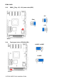
Quick Installation Guide 2.4 Audio / USB Daughter Board User’s Guide 2.4.1 Jumper and Connector Layout 2.4.2 Jumper and Connector List Jumpers Label Function Note JP6 Line out / Speaker out select (The speaker 1-3, 2-4 Speaker out out function is only available in combine 3-5, 4-6 Line out (Default) used of main board) Connectors Label Function Note CN1, CN2 USB 1.1/2.
ECM-LX800D 2.4.3 Setting Jumper and Connector Line out / Speaker out Select (JP6) 2.54mm USB 1.1/2.0 Connector 1 (JP1) Line Out* Signal PIN PIN Signal +5V 1 2 GND D1- 3 4 GND D1+ 5 6 D2+ GND 7 8 D2- GND 9 10 +5V Speaker Out Note: Wrong USB cable configuration with your USB devices might cause your USB devices damaged. 2.