ECM-LX800D 3.5” AMD LX800 Micro Module User’s Manual 1st Ed – 11 December 2008 Part No.
ECM-LX800D FCC Statement THIS DEVICE COMPLIES WITH PART 15 FCC RULES. OPERATION IS SUBJECT TO THE FOLLOWING TWO CONDITIONS: (1) THIS DEVICE MAY NOT CAUSE HARMFUL INTERFERENCE. (2) THIS DEVICE MUST ACCEPT ANY INTERFERENCE RECEIVED INCLUDING INTERFERENCE THAT MAY CAUSE UNDESIRED OPERATION. THIS EQUIPMENT HAS BEEN TESTED AND FOUND TO COMPLY WITH THE LIMITS FOR A CLASS "A" DIGITAL DEVICE, PURSUANT TO PART 15 OF THE FCC RULES.
User’s Manual Disclaimer Aualue Technology Inc. reserves the right to make changes, without notice, to any product, including circuits and/or software described or contained in this manual in order to improve design and/or performance.
ECM-LX800D Product Warranty Aualue warrants to you, the original purchaser, that each of its products will be free from defects in materials and workmanship for two years from the date of purchase. This warranty does not apply to any products which have been repaired or altered by persons other than repair personnel authorized by Aualue, or which have been subject to misuse, abuse, accident or improper installation.
User’s Manual Contents 1. Getting Started ............................................................................................................ 8 1.1 Safety Precautions .................................................................................................... 8 1.2 Packing List ............................................................................................................... 8 1.3 Document Amendment History ......................................................................
ECM-LX800D 3.5 Main Menu .............................................................................................................. 40 3.5.1 Standard CMOS Features .............................................................................................................. 41 3.5.2 Advanced BIOS Features............................................................................................................... 43 3.5.3 Advanced Chipset Features ..................................................
User’s Manual 8. EISA Configuration Is Not Complete PLEASE RUN EISA CONFIGURATION UTILITY ................... 81 9. ERROR ENCOUNTERED INITIALIZING HARD DRIVE.................................................................... 81 10. ERROR INITIALIZING HARD DISK CONTROLLER ..................................................................... 81 11. FLOPPY DISK CNTRLR ERROR OR NO CNTRLR PRESENT ................................................... 81 12.
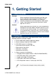
ECM-LX800D 1. Getting Started 1.1 Safety Precautions Warning! Always completely disconnect the power cord from your chassis whenever you work with the hardware. Do not make connections while the power is on. Sensitive electronic components can be damaged by sudden power surges. Only experienced electronics personnel should open the PC chassis. Caution! Always ground yourself to remove any static charge before touching the CPU card. Modern electronic devices are very sensitive to static electric charges.
User’s Manual 1.3 Document Amendment History Revision 1 st Date Dec.
ECM-LX800D 1.4 Manual Objectives This manual describes in detail the Aualue Technology ECM-LX800D Single Board. We have tried to include as much information as possible but we have not duplicated information that is provided in the standard IBM Technical References, unless it proved to be necessary to aid in the understanding of this board. We strongly recommend that you study this manual carefully before attempting to interface with ECM-LX800D or change the standard configurations.
User’s Manual 1.5 System Specifications System Onboard AMD Geode LX800 @ 0.9 W 500 MHz CPU Note: Available in different CPU speeds by request BIOS Award 4 Mbit Flash BIOS System Chipset AMD Geode LX 800/CS5536 I/O Chip Winbond W83627HG-AW System Memory Onboard 256MB DDR Memory, optional 512MB SSD One CompactFlash Type I/II socket Watchdog Timer Reset: 1 sec.~255 min. and 1 sec. or 1 min.
ECM-LX800D Mechanical & Environmental Power Requirement +12V~+20V Power Type AT/ATX Operation Temperature 0~60oC (32~140o F) Operating Humidity 0%~90% relative humidity, non-condensing Size ( L x W ) 5.7" x 4" (146 mm x 101 mm) Weight 0.44 lbs (0.
User’s Manual 1.6 Architecture Overview—Block Diagram The following block diagram shows the architecture and main components of ECM-LX800D. The following sections provide detail information about the functions provided onboard.
ECM-LX800D 2.
User’s Manual 2.
ECM-LX800D 2.2 Installation Procedure This chapter explains you the instructions of how to setup your system. 1. Turn off the power supply. 2. Insert the DIMM module (be careful with the orientation). 3. Insert all external cables for hard disk, floppy, keyboard, mouse, USB etc. except for flat panel. A CRT monitor must be connected in order to change CMOS settings to support flat panel. 4. Connect power supply to the board via the ATXPWR. 5. Turn on the power. 6.
User’s Manual 2.3 Jumper and Connector List You can configure your board to match the needs of your application by setting jumpers. A jumper is the simplest kind of electric switch. It consists of two metal pins and a small metal clip (often protected by a plastic cover) that slides over the pins to connect them. To “close” a jumper you connect the pins with the clip. To “open” a jumper you remove the clip. Sometimes a jumper will have three pins, labeled 1, 2, and 3.
ECM-LX800D Connectors Label Function Note CFCARD CompactFlash card connector Type I/II x 1 COM1 Serial port 1 connector D-sub 9-pin, male IDE Primary IDE connector 22 x 2 header, pitch 2.0mm JAUDIO Audio connector 5 x 2 header, pitch 2.0mm JBKL LCD inverter connector 5 x 1 wafer, pitch 2.0mm JCOM2 Serial port 2 in RS-232 mode connector 5 x 2 header, pitch 2.0mm JDIO General purpose I/O connector 5 x 2 header, pitch 2.0mm JIR IrDA connector 5 x 1 header, pitch 2.
User’s Manual 2.4 Setting Jumpers & Connectors 2.4.1 AT/ATX select (JAT/ATX) ATX* AT * Default 2.4.
ECM-LX800D 2.4.3 COM1-Ring, +5V, +12V power select(JRI1) Ring* VIN +5V VIN=input voltage of power. (+10V~+28V) * Default 2.4.
User’s Manual 2.4.5 LCD inverter connector (JBKL) Signal PIN +5V 5 VR 4 ENBKL 3 GND 2 VIN 1 Note: The power input voltage (VIN) equals to output voltage of inverter. Note: For inverters with adjustable Backlight function, it is possible to control the LCD brightness through the VR signal controlled by JVR. Please see the JVR section for detailed circuitry information. 2.4.5.1 Signal Description – LCD Inverter Connector (JBKL) Signal Signal Description VR Vadj = 0.75V ~ 4.
ECM-LX800D 2.4.6 2.4.
User’s Manual 2.4.8 2.4.9 Serial port 2 COM2 in RS-232 Mode (JCOM2) Signal PIN PIN Signal NC 10 9 RI CTS 8 7 RTS DSR 6 5 GND DTR 4 3 TxD RxD 2 1 DCD Signal PIN PIN Signal +5V 5 6 GND TxD+ 3 4 RxD+ TxD- 1 2 RxD- Serial port 2 in RS-422/485 Mode (JRS422/485) Note: JRS422/485 is available after modifying the mode of COM2 in BIOS setting.
ECM-LX800D 2.4.8.1 Signal Description – Serial Port Connector (JCOM2, JRS422/485) Signal Signal Description Serial output. This signal sends serial data to the communication link. The signal is TxD set to a marking state on hardware reset when the transmitter is empty or when loop mode operation is initiated. RxD DTR DSR RTS CTS DCD RI Serial input. This signal receives serial data from the communication link. Data Terminal Ready.
User’s Manual 2.4.10 LCD Backlight Brightness Adjustment Connector (JVR) 2.4.11 PIN Signal 1 GND 2 VR 3 +5V General purpose I/O connector (JDIO1) Signal PIN PIN Signal DI0 1 2 DO0 DI1 3 4 DO1 DI2 5 6 DO2 DI3 7 8 DO3 +5V 9 10 GND 2.4.10.1 Signal Description – General Purpose I/O Connector (JDIO1) Signal GP [0:3] Signal Description General purpose I/O port 1 bit 0~3.
ECM-LX800D 2.4.
User’s Manual 2.4.13 USB Connector 0 & 1 (JUSB) Signal PIN PIN Signal +5V 10 9 GND D1- 8 7 GND D1+ 6 5 D0+ GND 4 3 D0- GND 2 1 +5V 2.4.13.1 Signal Description – USB Connector 0&1 Connector(JUSB) Signal D0+/- D1+/- Signal Description Differential bi-directional data signal for USB channel 0 . Clock is transmitted along with the data using NRZI encoding. The signalling bit rate is up to 12 Mbs. Differential bi-directional data signal for USB channel 1.
ECM-LX800D 2.4.14 LVDS Connector (JLVDS) 18-bit Signal PIN PIN Signal +3.3V 19 20 +5V +3.3V 17 18 +5V SMB_DAT 15 16 SMB_CLK GND 13 14 GND Txclk 11 12 Txclk# NC 9 10 NC Txout2 7 8 Txout2# Txout1 5 6 Txout1# Txout0 3 4 Txout0# GND 1 2 GND 24-bit (Optional) Signal PIN PIN Signal +3.3V 19 20 +5V +3.
User’s Manual 2.4.15 TFT Panel Connector (JTFT) Signal PIN PIN Signal ENBKL 39 40 NC LDEMOD 37 38 HSYNC SHCLK 35 36 VSYNC GND 33 34 GND P22 31 32 P23 P20 29 30 P21 P18 27 28 P19 P16 25 26 P17 P14 23 24 P15 P12 21 22 P13 P10 19 20 P11 P8 17 18 P9 P6 15 16 P7 P4 13 14 P5 P2 11 12 P3 P0 9 10 P1 NC 7 8 GND +3.3V 5 6 +3.3V GND 3 4 GND +5V 1 2 +5V 2.4.15.
ECM-LX800D 2.4.15.
User’s Manual 2.4.
ECM-LX800D 2.4.
User’s Manual 2.4.17.1 Signal Description – Primary IDE Connector (IDE) Signal IDE_ [2:0] PDCS0#, PDCS1# PDD [15:0] PDIOR# PDIOW# PIORDY Signal Description IDE Address Bits. These address bits are used to access a register or data port in a device on the IDE bus. IDE Chip Selects. The chip select signals are used to select the command block registers in an IDE device. DCS1# selects the primary hard disk. IDE Data Lines. D [15:0] transfers data to/from the IDE devices. IDE I/O Read.
ECM-LX800D 2.4.18 PS/2 keyboard & mouse connector(KB/MS) 2.4.19 Signal PIN PIN Signal MCLK 8 6 KCLK +5V 5 3 GND MDAT 2 1 KDAT VGA Connector (JVGA1) Signal RED PIN Signal 6 GND 1 11 7 GREEN 2 GND 12 8 BLUE 3 13 HSYNC 4 VCC 14 VSYNC 10 GND 5 DAT GND 9 NC NC GND 15 DCK 2.4.17.1 Signal Description – VGA Connector (JVGA1) Signal Signal Description HSYNC CRT horizontal synchronisation output. VSYNC CRT vertical synchronisation output.
User’s Manual DAT Display Data Channel Data. Used as data signal to/from monitors with DDC interface. Analog output carrying the red colour signal to the CRT. For 75 Ω cable RED impedance. Analog output carrying the green colour signal to the CRT. For 75 Ω cable GREEN impedance. Analog output carrying the blue colour signal to the CRT. For 75 Ω cable BLUE impedance.
ECM-LX800D 3.
User’s Manual 3.1 Starting Setup The AwardBIOS™ is immediately activated when you first power on the computer. The BIOS reads the system information contained in the CMOS and begins the process of checking out the system and configuring it. When it finishes, the BIOS will seek an operating system on one of the disks and then launch and turn control over to the operating system.
ECM-LX800D 3.2 Using Setup In general, you use the arrow keys to highlight items, press to select, use the PageUp and PageDown keys to change entries, press for help and press to quit. The following table provides more detail about how to navigate in the Setup program using the keyboard.
User’s Manual To Display a Sub Menu Use the arrow keys to move the cursor to the sub menu you want. Then press . A “” pointer marks all sub menus. 3.3 Getting Help Press F1 to pop up a small help window that describes the appropriate keys to use and the possible selections for the highlighted item. To exit the Help Window press or the F1 key again. 3.
ECM-LX800D 3.5 Main Menu Once you enter the AwardBIOS™ CMOS Setup Utility, the Main Menu will appear on the screen. The Main Menu allows you to select from several setup functions and two exit choices. Use the arrow keys to select among the items and press to accept and enter the sub-menu. Note that a brief description of each highlighted selection appears at the bottom of the screen.
User’s Manual 3.5.1 Standard CMOS Features The items in Standard CMOS Setup Menu are divided into few categories. Each category includes no, one or more than one setup items. Use the arrow keys to highlight the item and then use the or keys to select the value you want in each item. 3.5.1.1 Main Menu Selection This reference table shows the selections that you may make on the Main Menu.
ECM-LX800D 3.5.1.2 IDE Adapter Setup The IDE adapters control the hard disk drive. Use a separate sub menu to configure each hard disk drive. The below Figure will shows the IDE primary master sub menu. Item Options IDE HDD Auto-detection Press Enter IDE Primary Master IDE Primary Slave, None Auto Manual Description Press Enter to auto-detect the HDD on this channel. If detection is successful, it fills the remaining fields on this menu.
User’s Manual 3.5.2 Advanced BIOS Features This section allows you to configure your system for basic operation. You have the opportunity to select the system’s default speed, boot-up sequence, keyboard operation, shadowing and security. 3.5.2.1 Virus Warning This item allows you to choose the VIRUS Warning feature for IDE Hard Disk boot sector protection. If this function is enabled and someone attempt to write data into this area, BIOS will show a warning message on screen and alarm beep.
ECM-LX800D 3.5.2.4 First/Second/Third/Other Boot Device The BIOS attempts to load the operating system from the devices in the sequence selected in these items. Item LS120 HDD-0 SCSI CDROM HDD-1 USB-FDD USB-ZIP USB-CDROM USB-HDD LAN Disabled Description LS120 Device Hard Disk Device 0 SCSI Device CDROM Device Hard Disk Device 1 USB Floppy Device USB ZIP Device USB CDROM Device USB Hard Disk Device Network Device Disabled any boot device 3.5.2.5 Boot Up NumLock Status Select power on state for NumLock.
User’s Manual Note: To disable security, select PASSWORD SETTING at Main Menu and then you will be asked to enter password. Do not type anything and just press , it will disable security. Once the security is disabled, the system will boot and you can enter Setup freely. 3.5.2.11 OS Select for DRAM > 64MB Select the operating system that is running with greater than 64MB of RAM on the system. Item Non-OS2 OS2 Description Disable OS for over 64 MB DRAM Enable OS for over 64 MB DRAM 3.5.2.
ECM-LX800D 3.5.3 Advanced Chipset Features This section allows you to configure the system based on the specific features of the installed chipset. This chipset manages bus speeds and access to system memory resources, such as DRAM and the external cache. It also coordinates communications between the conventional ISA bus and the PCI bus. It must be stated that these items should never need to be altered.
User’s Manual 3.5.3.3 CAS Latency It’s the time, in number of clock cycles, elapses after the memory controller sends a request to read a memory location and before the data is sent to the module’s output pins. The choices: Auto, 1.5, 2.0, 2.5, 3.0, 3.5 3.5.3.4 Video Memory Size This item allows to select video memory size. The choices: Disable, 8 M, 16 M, 32 M, 64 M, 128 M, 254 M. 3.5.3.5 Output Display This item allows to select video memory size. The choices: Flat Panel, CRT Monitor, Panel & CRT. 3.5.3.
ECM-LX800D The choices: Enabled, Disabled. 3.5.3.8 Onboard USB1.1 This item allows you to enable the onboard USB1.1 function. The choices: Enabled, Disabled. 3.5.3.9 Onboard USB2.0 This item allows you to enable the onboard USB2.0 function. The choices: Enabled, Disabled. 3.5.3.10 Onboard IDE This item allows you to enable the onboard IDE function. The choices: Enabled, Disabled. 3.5.3.11 Memory Hole At 15M-16M This item allows you to reserve the memory area for some specific ISA card’s use.
User’s Manual IDE Primary Master UDMA IDE Primary Slave UDMA Auto Disabled Ultra DMA implementation is possible only if your IDE hard drive supports it and the operating environment includes a DMA driver (Windows 95 OSR2 or a third-party IDE bus master driver). If the hard drive and the system software both support Ultra DMA, select Auto to enable BIOS support. IDE DMA Transfer Access Enabled Disabled This item allows to enable or disable DMA (Direct Memory Access) support for all IDE devices.
ECM-LX800D 3.5.4.1 IT8888 ISA Decode IO The decode I/O spaces can be programmed to claim PCI I/O cycle with Fast/Medium/Slow/Subtractive DEVSEL# (Device Select) timing speed. Item I/O Space 0 I/O Space 1 I/O Space 2 Options Description Enabled Disabled It allows you to allocate system resources to the ISA bridge and to enable I/O Speed 0 I/O Speed1 I/O Speed2 Subtractive Speed Slow Speed Medium Speed Fast Speed I/O Addr. 0 I/O Addr. 1 I/O Addr.
User’s Manual 3.5.4.2 IT8888 ISA Decode Memory The decode Memory spaces can be programmed to claim PCI Memory cycle with Fast/Medium/Slow/Subtractive DEVSEL# (Device Select) timing speed. It allows you to use the IT8888 ISA Decode Memory to set the resources for the onboard ISA bus. Item Options Memory Space 0 Memory Space 1 Enabled Disabled Description It allows you to allocate memory resources to the ISA bridge and to enablethe function correctly. . Memory Speed 0 Memory Speed 1 Memory Addr.
ECM-LX800D 3.5.5.2 Power Management Setup The Power Management Setup allows you to configure you system to most effectively save energy while operating in a manner consistent with your own style of computer use. 3.5.7.1 ACPI Suspend Type This determines the ACPI suspend type. The choices: S1(POS), S3(STR) 3.5.7.2 Power Management This category allows you to select the type (or degree) of power saving. The choices: Disabled,Legacy, APM, ACPI 3.5.7.
User’s Manual The choices: Instant-Off, Delay 4 Sec. 3.5.7.7 Power On By Alarm This determines whether to set the time the system boot up. When this function is enabled, you need to set the time (hh:mm:ss) to wake up your system. The choices: Disabled, Enabled. 3.5.7.8 IRQ Wakeup Events The VGA, LPT & COM, HDD & FDD, and PCI master are I/O events which can prevent the system from entering a power saving mode or can awaken the system from such a mode.
ECM-LX800D 3.5.6.2 PnP / PCI Configuration This section describes configuring the PCI bus system. PCI, or Personal Computer Interconnect, is a system which allows I/O devices to operate at speeds nearing the speed the CPU itself uses when communicating with its own special components. This section covers some very technical items and it is strongly recommended that only experienced users should make any changes to the default settings. 3.5.8.
User’s Manual this field to “manual” choose specific resources by going into each of the sub menu that follows this field (a sub menu is preceded by a “”). The choices: Auto(ESCD), Manual. 3.5.8.5 PCI/VGA Palette Snoop This item allows you to decide if your graphics card should allow VGA palete snooping by a fixed function display card. It is only useful if your use a fixed function display card that requires a VGA-compatible graphics card to be present (i.e. MPEG decoder card).
ECM-LX800D 3.5.9.2 Load Optimized Defaults Use this menu to load the BIOS default values that are factory settings for optimal performance system operations. While Award has designed the custom BIOS to maximize performance, the factory has the right to change these defaults to meet their needs. Press to load the default values setting for optimal performance system operations.
User’s Manual 3.5.10.2 Set Supervisor / User Password You can set either supervisor or user password, or both of them. Supervisor Password: able to enter/change the options of setup menus. User Password: able to enter but no right to change the options of setup menus.
ECM-LX800D Type the password, up to eight characters in length, and press . The password typed now will clear any previously entered password from CMOS memory. You will be asked to confirm the password. Type the password again and press . You may also press to abort the selection and not enter a password. To disable a password, just press when you are prompted to enter the password. A message will confirm the password will be disabled.
User’s Manual PASSWORD DISABLED. When a password has been enabled, you will be prompted to enter it every time you try to enter Setup. This prevents an unauthorized person from changing any part of your system configuration. Additionally, when a password is enabled, you can also require the BIOS to request a password every time your system is rebooted. This would prevent unauthorized use of your computer.
ECM-LX800D 3.5.12.2 Exit Without Save Abandon all CMOS value changes and exit setup, and the system is restarted after exiting.
User’s Manual 4 Drivers Installation Note: Installation procedures and screen shots in this section are for your reference and may not be exactly the same as shown on your screen.
ECM-LX800D 4.1 Install Audio Driver (For AMD LX800) Insert the Supporting CD-ROM to CD-ROM drive, and it should show the index page of Evalue’s products automatically. If not, locate Index.htm and choose the product from the menu left, or link to \Driver_Audio\AMD\GX3. Note: The installation procedures and screen shots in this section are based on Windows XP operation system. Step 3. Select Multimedia Audio Controller to Reinstall Driver. Step1.
User’s Manual Step6. Click Continue Anyway to run the installation. Step7. Click Finish to complete the setup.
ECM-LX800D 4.2 Install Chipset Driver (For AMD LX800) Insert the Supporting CD-ROM to CD-ROM drive, and it should show the index page of Evalue’s products automatically. If not, locate Index.htm and choose the product from the menu left, or link to \Driver_Chipset\AMD\GX3. Note: The installation procedures and screen shots in this section are based on Windows XP operation system. Step 3. Select Entertainment… to Reinstall Driver. Step1.
User’s Manual Step6. The setup will install automatically. Step7. Click Finish to complete the setup.
ECM-LX800D 4.3 Install PCI to ISA Bridge Driver (For ITE IT8888) Insert the Supporting CD-ROM to CD-ROM drive, and it should show the index page of Evalue’s products automatically. If not, locate Index.htm and choose the product from the menu left, or link to \Driver_Chipset\AMD\GX3\PCI to ISA Bridge. Note: The installation procedures and screen shots in this section are based on Windows XP operation system. Step 3. Select Other PCI Bridge Device to Reinstall Driver. Step1.
User’s Manual Step6. The setup will install automatically. Step7. Click Finish to complete the setup.
ECM-LX800D 4.4 Install Display Driver (For AMD LX800) Insert the Supporting CD-ROM to CD-ROM drive, and it should show the index page of Evalue’s products automatically. If not, locate Index.htm and choose the product from the menu left, or link to \Driver_Video\AMD\GX3. Note: The installation procedures and screen shots in this section are based on Windows XP operation system. Step 3. Select Video Controller (VGA Compatible to Reinstall Driver. Step1.
User’s Manual Step6. Click Continue Anyway to run the installation. Step7. Click Finish to complete the setup.
ECM-LX800D 4.5 Install Ethernet Driver (For Realtek RTL810x, RTL813x Family) Insert the Supporting CD-ROM to CD-ROM drive, and it should show the index page of Aualue’s products automatically. If not, locate Index.htm and choose the product from the menu left, or link to \Driver_Network\Realtek\ RTL810x_813X Family. Note: The installation procedures and screen shots in this section are based on Windows XP operation system. Step 1. Locate 「\Driver_Network\Realtek\ RTL810x_813X Family\Setup.exe」. Step 2.
User’s Manual 5 Mechanical Drawing ECM-LX800D User’s Manual 71
ECM-LX800D Unit: mm 72 ECM-LX800D User’s Manual
User’s Manual Appendix A: Chipset Introduction AMD LX800 & CS5536 Realtek ALC203 Audio Codec Realtek RTL8101L Ethernet Controller ITE IT8888 PCI to ISA Bridge Compact Flash Interface ECM-LX800D User’s Manual 73
ECM-LX800D — AMD LX800 & CS5536 The AMD Geode™ LX 800@0.9W processor brings x86 power and versatility to applications for entertainment, business, education, and embedded markets. The AMD Geode LX processors’ integrated, innovative architecture delivers the most performance per watt available in the industry today, and can lead to longer battery life and enable small form-factor designs.
User’s Manual GeodeLink Memory Controller Graphics Processor Display Controller Video Processor Video Input Port GeodeLink PCI Bridge Security Block The AMD Geode™ CS5536 companion device works with both AMD Geode™ LX and AMD Geode™ GX processor families to create today's leading high-performance, low-power x86 solution for embedded applications, ranging from thin clients and digital set-top boxes to single-board computers and Personal Access Devices (PADs).
ECM-LX800D — Realtek ALC203 Audio Codec The ALC203 is a 20-bit DAC and 18-bit ADC full-duplex AC'97 2.3 compatible stereo audio CODEC designed for PC multimedia systems, including host/soft audio, and AMR/CNR based designs. The ALC203 incorporates proprietary converter technology to achieve a high SNR (greater than 100 dB), sensing logics for device reporting, and a Universal Audio Jack® for improved user convenience.
User’s Manual PCI Vital Product Data (VPD) is also supported to provide the information that uniquely identifies hardware (i.e., the OEM brand name of RTL8101L LAN card). The information may consist of part number, serial number, and other detailed information. To provide cost down support, the RTL8101L is capable of using a 25MHz crystal or OSC as its internal clock source. The RTL8101L keeps network maintenance costs low and eliminates usage barriers.
ECM-LX800D The Compact Flash storage card is O/S independent, thus offering an optimal solution for embedded systems operating in non-standard computing environments. The Compact Flash storage card is IDE compatible and offers various capacities.
User’s Manual Appendix B: AWARD BIOS POST Messages ECM-LX800D User’s Manual 79
ECM-LX800D Overview During the Power On Self-Test (POST), if the BIOS detects an error requiring you to do something to fix, it will either sound a beep code or display a message. If a message is displayed, it will be accompanied by: PRESS F1 TO CONTINUE OR PRESS DEL TO ENTER SETUP Post Beep Currently there are two kinds of beep codes in BIOS. This code indicates that a video error has occurred and the BIOS cannot initialize the video screen to display any additional information.
User’s Manual 5. DISPLAY SWITCH IS SET INCORRECTLY Display switch on the motherboard can be set to either monochrome or color. This indicates the switch is set to a different setting than indicated in Setup. Determine which setting is correct, and then either turn off the system and change the jumper, or enter Setup and change the VIDEO selection. 6. DISPLAY TYPE HAS CHANGED SINCE LAST BOOT Since last powering off the system, the display adapter has been changed.
ECM-LX800D 12. Invalid EISA Configuration PLEASE RUN EISA CONFIGURATION UTILITY The non-volatile memory containing EISA configuration information was programmed incorrectly or has become corrupt. Re-run EISA configuration utility to correctly program the memory. Note: When either of these errors appears, the system will boot in ISA mode, which allows you to run the EISA Configuration Utility. 13. KEYBOARD ERROR OR NO KEYBOARD PRESENT Cannot initialize the keyboard.
User’s Manual 20. PRESS A KEY TO REBOOT This will be displayed at the bottom screen when an error occurs that requires you to reboot. Press any key and the system will reboot. 21. PRESS F1 TO DISABLE NMI, F2 TO REBOOT When BIOS detects a Non-maskable Interrupt condition during boot, this will allow you to disable the NMI and continue to boot, or you can reboot the system with the NMI enabled. 22. RAM PARITY ERROR - CHECKING FOR SEGMENT ... Indicates a parity error in Random Access Memory. 23.
ECM-LX800D 27. Wrong Board In Slot PLEASE RUN EISA CONFIGURATION UTILITY The board ID does not match the ID stored in the EISA non-volatile memory. Note: When either of these errors appears, the system will boot in ISA mode, which allows you to run the EISA Configuration Utility. 28. FLOPPY DISK(S) fail (80) Unable to reset floppy subsystem. 29. FLOPPY DISK(S) fail (40) Floppy Type dismatch. 30. Hard Disk(s) fail (80) HDD reset failed. 31. Hard Disk(s) fail (40) HDD controller diagnostics failed.
User’s Manual 40. POST Codes Please take reference to Phoenix-Award website for the latest post codes. http://www.phoenix.com/NR/rdonlyres/0835996A-6694-4F6D-8243-1030EE040D92/0/post code.pdf 40.1 Normal POST Code Note: EISA POST codes are typically output to port address 300h. ISA POST codes are output to port address 80h. Code (hex) Name Description C0 Turn Off Chipset and OEM Specific-Cache control cache CPU test Processor Status (1FLAGS) Verification.
ECM-LX800D Code (hex) Name Description 3 Early Superio Init Early Initialized the super IO 4 Reserved 5 Blank video 6 Reserved 7 Init KBC Keyboard controller init 8 KB test Test the Keyboard 9 Reserved A Mouse Init Initialized the mouse B Onboard Audio init Onboard audio controller initialize if exist C Reserved D Reserved E CheckSum Check F Reserved 10 Auto detec EEPROM Reset Video controller Check the intergraty of the ROM, BIOS and message Check Flash type and copy f
User’s Manual Code (hex) Name 25 Reserved 26 Reserved 27 KBC final Init 28 Reserved 29 Initialize Video Interface Description Final Initial KBC and setup BIOS data area Read CMOS location 14h to find out type of video in use. Detect and Initialize Video Adapter. 2A Reserved 2B Reserved 2C Reserved 2D Video memory test Test video memory, write sign-on message to screen. Setup shadow RAM - Enable shadow according to Setup.
ECM-LX800D Code (hex) Name Description 43 Test Stuck 8259's Turn off interrupts then verify no interrupt mask register is on. Interrupt Bits Test 8259 Interrupt Force an interrupt and verify the interrupt occurred. Functionality 44 Reserved 45 Reserved 46 Reserved 47 Set EISA Mode If EISA non-volatile memory checksum is good, execute EISA initialization. If not, execute ISA tests an clear EISA mode flag.
User’s Manual Code (hex) Name 5E Reserved 5F Reserved 60 Setup enable 61 Reserved 62 Reserved 63 Initialize & Install Detect if mouse is present, initialize mouse, install interrupt Mouse vectors.
ECM-LX800D Code (hex) Name Description 7D Reserved 7E Reserved 7F POST error check 80 Reserved 81 Reserved 82 Security Check Ask password security (optional). 83 Write CMOS Write all CMOS values back to RAM and clear screen. 84 Pre-boot Enable Enable parity checker. Enable NMI, Enable cache before boot. 85 Initialize Option ROMs Initialize any option ROMs present from C8000h to EFFFFh.
User’s Manual 40.2 Quick POST Codes Code (hex) Name Description 65 Init onboard device Early Initialized the super IO. Reset Video controller. Keyboard controller init Test the Keyboard Initialized the mouse Onboard audio controller initialize if exist.
ECM-LX800D Code (hex) Name Description 72 Install FDD Enter setup check and auto11 configuration check up Initialize floppy disk drive controller and any drives. Install FDD and setup BIOS data area parameters 73 Install FDD Initialize hard drive controller and any drives. IDE device detection and install Initialize any serial and parallel ports (also game port). 74 Detect & Initialize Math Initialize math coprocessor.
User’s Manual 40.3 S4 POST Codes Code (hex) Name Description 5A Early Chipset Init Early Initialized the super IO. Reset Video controller. Keyboard controller init. Test the Keyboard Initilized the mouse 5B Cmos Check Check Cmos Circuitry and reset CMOS 5C Chipset default Prog Program the chipset registers with CMOS values.
ECM-LX800D 40.4 BootBlock POST Codes Code (hex) Name Description 1 Base memory test Clear base memory area (0000:0000--9000:ffffh) 5 KB init Initialized 12 Install interrupt vectors Install int.