ECM-LX800W Series 3.5” AMD LX800 Wide Temp Micro Module Quick Installation Guide 1st Ed – 15 December, 2010 Part No.
ECM-LX800W Series Contents 1. Getting Started ............................................................................................................ 3 1.1 Safety Precautions ................................................................................................ 3 1.2 Packing List ........................................................................................................... 3 2. Hardware Configuration .............................................................................
Quick Installation Guide 1. Getting Started 1.1 Safety Precautions Warning! Always completely disconnect the power cord from your chassis whenever you work with the hardware. Do not make connections while the power is on. Sensitive electronic components can be damaged by sudden power surges. Only experienced electronics personnel should open the PC chassis. Caution! Always ground yourself to remove any static charge before touching the CPU card.
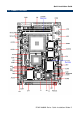
ECM-LX800W Series 2.
Quick Installation Guide 2.
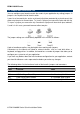
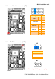
ECM-LX800W Series 2.2 Jumper and Connector List You can configure your board to match the needs of your application by setting jumpers. A jumper is the simplest kind of electric switch. It consists of two metal pins and a small metal clip (often protected by a plastic cover) that slides over the pins to connect them. To “close” a jumper you connect the pins with the clip. To “open” a jumper you remove the clip. Sometimes a jumper will have three pins, labeled 1, 2, and 3.
Quick Installation Guide Connectors Label Function Note COM1 Serial port 1 connector D-sub 9-pin, male CF Card CompactFlash card connector Type I/II x 1 IDE Primary IDE connector 22 x 2 header, pitch 2.0mm JAUDIO Audio connector 5 x 2 header, pitch 2.0mm JBKL LCD inverter connector 5 x 1 wafer, pitch 2.0mm JCDIN CD-ROM audio input connector 4 x 1 wafer, pitch 2.0mm JCOM2 JCOM3 Serial port 2 connector Serial port 3 connector 5 x 2 header, pitch 2.
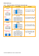
ECM-LX800W Series 2.3 Setting Jumpers & Connectors 2.3.1 Clear CMOS (JBAT) Protect* Clear CMOS * Default 2.3.
Quick Installation Guide 2.3.3 Front Panel Power selector (JFP) Signal PIN + 1 - 2 PWBT 3 PWR MSEL 4 + 5 - 6 - 7 + 8 + 9 - 10 PWR-LED HDD-LED CASE OPEN# * Default 2.3.
ECM-LX800W Series Signal Description –AT/ ATX mode & Input power type 2.3.4.1 Input power type Power-ON Mode Description AT Mode AT Type (PWR MSEL) Use AT type power input, and set the board in AT mode. 1) Connect to power supply ATX Mode (PWR MSEL) 2) JUMP Use AT type power input, and set the board in ATX mode. ATX Type AT Mode (PWR MSEL) Use ATX type power input, and set the board in AT mode.
Quick Installation Guide 2.3.5 SATA Power connector (SATA_PWR1/ SATA_PWR2) SATA_PWR2 SATA_PWR1 Signal PIN +5V 1 GND 2 * Default 2.3.6 LPC connector (LPC1) Signal PIN PIN Signal LAD0 1 2 +3.
ECM-LX800W Series 2.3.7 2.3.
Quick Installation Guide 2.3.9 LCD inverter connector (JBKL) Signal PIN +12V 1 GND 2 ENBKL 3 VR 4 +5V 5 Note: For inverters with adjustable Backlight function, it is possible to control the LCD brightness through the VR signal controlled by JVR. Please see the JVR section for detailed circuitry information. 2.3.9.1 Signal Description – LCD Inverter Connector (JBKL) Signal Signal Description VR Vadj = 0.75V ~ 4.25V (Recommended: 4.
ECM-LX800W Series 2.3.10 2.3.
Quick Installation Guide 2.3.12 Serial port 3, 4 connector (JCOM3, JCOM4) JCOM3 JCOM4 2.3.
ECM-LX800W Series 2.3.
Quick Installation Guide 2.3.15 LVDS Connector (JLVDS) Signal PIN PIN Signal +3.3V 19 20 +5V +3.3V 17 18 +5V I C_DAT 15 16 I C_CLK GND 13 14 GND TxCLK 11 12 TxCLK# Txout3 9 10 Txout3# Txout2 7 8 Txout2# Txout1 5 6 Txout1# Txout0 3 4 Txout0# GND 1 2 GND 2 2 2.3.15.1 Signal Description – LVDS Connector (JLVDS) Signal Description 2 2 2 I C_DAT, I C_CLK I C interface for panel parameter EEPROM. This EERPOM is mounted on the LVDS receiver.
ECM-LX800W Series 2.3.16 TFT Panel Connector (JTFT) 18 ECM-LX800W Series Quick Installation Guide Signal PIN PIN Signal ENBKL 39 40 NC LDEMOD 37 38 HSYNC SHCLK 35 36 VSYNC GND 33 34 GND R6 31 32 R7 R4 29 30 R5 R2 27 28 R3 R0 25 26 R1 G6 23 24 G7 G4 21 22 G5 G2 19 20 G3 G0 17 18 G1 B6 15 16 B7 B4 13 14 B5 B2 11 12 B3 B0 9 10 B1 NC 7 8 GND +3.3V 5 6 +3.
Quick Installation Guide 2.3.16.1 Signal Description – TFT Panel Connector (JTFT) Signal P [0:23] Description Flat panel data output for 18/24 bit TFT flat panels. Refer to table below for configurations for various panel types. The flat panel data and control outputs are all on-board controlled for secure power-on/off sequencing SHFCLK Shift Clock.
ECM-LX800W Series 2.3.17 2.3.
Quick Installation Guide 2.3.
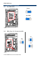
ECM-LX800W Series 2.4 Audio / USB Daughter Board User’s Guide 2.4.1 Jumper and Connector Layout 2.4.2 Jumper and Connector List Jumpers Label Function Note JP6 Line out / Speaker out select (The speaker 1-3, 2-4 Speaker out out function is only available in combine 3-5, 4-6 Line out (Default) used of main board) Connectors Label Function CN1, CN2 USB 1.1/2.
Quick Installation Guide 2.4.3 Setting Jumper and Connector Line out / Speaker out Select (JP6) 2.54mm USB 1.1/2.0 Connector 1 (JP1) Line Out* Signal PIN PIN Signal +5V 1 2 GND D1- 3 4 GND D1+ 5 6 D2+ GND 7 8 D2- GND 9 10 +5V Speaker Out Note: Wrong USB cable configuration with your USB devices might damage your USB devices. 2.
ECM-LX800W Series Technical Support We want you to get the maximum performance from your products. So if you run into technical difficulties, we are here to help. For the most frequently asked questions, you can easily find answers in your product documentation. These answers are normally a lot more detailed than the ones we can give over the phone. So please consult the user’s manual first. To receive the latest version of the user’s manual; please visit our Web site at: http://www.avalue.com.