ECM-QB 3.5" Intel Queensbay Micro Module Quick Installation Guide 1st Ed – 24 October 2011 Part No.
ECM-QB Quick Installation Guide FCC Statement THIS DEVICE COMPLIES WITH PART 15 FCC RULES. OPERATION IS SUBJECT TO THE FOLLOWING TWO CONDITIONS: (1) THIS DEVICE MAY NOT CAUSE HARMFUL INTERFERENCE. (2) THIS DEVICE MUST ACCEPT ANY INTERFERENCE RECEIVED INCLUDING INTERFERENCE THAT MAY CAUSE UNDESIRED OPERATION. THIS EQUIPMENT HAS BEEN TESTED AND FOUND TO COMPLY WITH THE LIMITS FOR A CLASS "A" DIGITAL DEVICE, PURSUANT TO PART 15 OF THE FCC RULES.
ECM-QB Quick Installation Guide Content 1. Getting Started ............................................................................................................ 4 1.1 Safety Precautions.................................................................................................. 4 1.2 Packing List ............................................................................................................ 4 2. Hardware Configuration .............................................................
ECM-QB Quick Installation Guide 1. Getting Started 1.1 Safety Precautions Warning! Always completely disconnect the power cord from your chassis whenever you work with the hardware. Do not make connections while the power is on. Sensitive electronic components can be damaged by sudden power surges. Only experienced electronics personnel should open the PC chassis. Caution! Always ground yourself to remove any static charge before touching the CPU card.
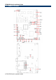
ECM-QB Quick Installation Guide 2.
ECM-QB Quick Installation Guide 2.
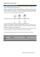
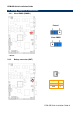
ECM-QB Quick Installation Guide 2.2 Jumper and Connector List You can configure your board to match the needs of your application by setting jumpers. A jumper is the simplest kind of electric switch. It consists of two metal pins and a small metal clip (often protected by a plastic cover) that slides over the pins to connect them. To “close” a jumper you connect the pins with the clip. To “open” a jumper you remove the clip. Sometimes a jumper will have three pins, labeled 1, 2, and 3.
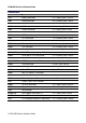
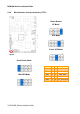
ECM-QB Quick Installation Guide Connectors Label Function Note BT1 Battery connector 2 x 1 wafer, pitch 1.25 mm CN1 Audio connector 6 x 2 header, pitch 2.0 mm CN2 LVDS connector 2 x 20 header, pitch 1.25mm CN3 LCD inverter connector 5 x 1 wafer, pitch 2.0mm CN4 Power connector 2 x 2 wafer, pitch 4.2 mm CN5 CAN connector 4 x 1 wafer, pitch 2.54 mm CN6 USB 2 & 3 connector 5 x 2 header, pitch 2.0 mm CN7 LPC connector 7 x 2 header, pitch 2.
ECM-QB Quick Installation Guide 2.3 Setting Jumpers & Connectors 2.3.1 Clear CMOS (CMOS1) Protect* Clear CMOS * Default 2.3.
ECM-QB Quick Installation Guide 2.3.
ECM-QB Quick Installation Guide 2.3.4 Audio connector (CN1) Signal 2.3.
ECM-QB Quick Installation Guide 2.3.
ECM-QB Quick Installation Guide 2.3.7 LCD Inverter Connector (CN3) Signal PIN +12V 1 GND 2 BLKTEN_OVL 3 BRIGHT 4 +5V 5 Note: For inverters with adjustable Backlight function, it is possible to control the LCD brightness through the VR signal controlled by JVR. 2.3.7.1 Signal Description – LCD Inverter Connector (CN3) Signal Signal Description BRIGHT Vadj = 0.75V ~ 4.25V (Recommended: 4.
ECM-QB Quick Installation Guide 2.3.8 CAN connector (CN5) Signal PIN 2.4.
ECM-QB Quick Installation Guide 2.3.10 LPC connector (CN7) Signal 2.3.
ECM-QB Quick Installation Guide 2.3.12 Serial port 2/3 connector (CN9 / CN11) CN9 CN11 CN11 Signal CN9 2.3.
ECM-QB Quick Installation Guide 2.3.14 Serial port 4 in RS-422 mode (CN15) Signal 2.3.
ECM-QB Quick Installation Guide 2.3.16 General purpose I/O connector (DIO1) Signal PIN PIN DI0 1 2 DO10 DI1 3 4 DO11 DI2 5 6 DO12 DI3 7 8 DO13 DI4 9 10 DO14 DI5 11 12 DO15 DI6 13 14 DO16 DI7 15 16 DO17 SMB_CLK 17 GND 2.3.
ECM-QB Quick Installation Guide 2.3.18 2.3.
ECM-QB Quick Installation Guide 2.3.