ECM-QM77 Intel® Ivy Bridge Processors 3.5” Micro Module with Intel® QM77 Chipset Quick Installation Guide 5th Ed – 03 September 2013 Part No.
ECM-QM77 Quick Installation Guide 1. Getting Started 1.1 Safety Precautions Warning! Always completely disconnect the power cord from your chassis whenever you work with the hardware. Do not make connections while the power is on. Sensitive electronic components can be damaged by sudden power surges. Only experienced electronics personnel should open the PC chassis. Caution! Always ground yourself to remove any static charge before touching the CPU card.
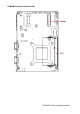
ECM-QM77 Quick Installation Guide 2.
ECM-QM77 Quick Installation Guide 2.
ECM-QM77 Quick Installation Guide ECM-QM77 Quick Installation Guide 5
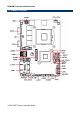
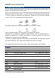
ECM-QM77 Quick Installation Guide 2.2 Jumper and Connector List You can configure your board to match the needs of your application by setting jumpers. A jumper is the simplest kind of electric switch. It consists of two metal pins and a small metal clip (often protected by a plastic cover) that slides over the pins to connect them. To “close” a jumper you connect the pins with the clip. To “open” a jumper you remove the clip. Sometimes a jumper will have three pins, labeled 1, 2, and 3.
ECM-QM77 Quick Installation Guide J422/1 COM 1 RS-422-485 mode 3 x 2 header, pitch 2.00 mm JAUDIO1 Audio connector 6 x 2 header, pitch 2.00 mm JBKL1 LCD inverter connector 5 x 1 wafer, pitch 2.00 mm JCOM2 Serial port 2 connector 5 x 2 header, pitch 2.00 mm JDIO1 General purpose I/O connector 6 x 2 header, pitch 2.00 mm JFP1 Miscellaneous setting connector 5 x 2 header, pitch 2.00 mm JLPC1 Low pin count interface 7 x 2 header, pitch 2.00 mm JLVDS1 LVDS connector 20 x 2 header, pitch 1.
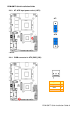
ECM-QM77 Quick Installation Guide 2.3 Setting Jumpers & Connectors 2.3.1 Clear CMOS (JBAT1) Protect* Clear CMOS * Default 2.3.
ECM-QM77 Quick Installation Guide 2.3.3 AT/ ATX Input power select (JAT1) AT* ATX * Default 2.3.
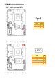
ECM-QM77 Quick Installation Guide 2.3.5 2.3.6 Battery connector (BAT1) Signal PIN +3.
ECM-QM77 Quick Installation Guide 2.3.7 2.3.
ECM-QM77 Quick Installation Guide 2.3.9 Audio connector (JAUDIO1) Signal PIN PIN GND 11 12 MIC1-JD LINE1-JD 9 10 FRONT-JD MIC1-L-IN 7 8 MIC1-R-IN LINE1-L-IN 5 6 LINE1-R-IN GND 3 4 GND FRONT-L-OUT 1 2 FRONT-R-OUT 2.3.9.
ECM-QM77 Quick Installation Guide 2.3.10 2.3.11 LCD inverter connector (JBKL1) Signal PIN +12V 1 GND 2 BKLEN 3 BRIADJ 4 +5V 5 LCD backlight brightness adjustment (JVR1) Signal PIN +5V 1 BRIGHT 2 GND 3 Variation Resistor (Recommended: 4.
ECM-QM77 Quick Installation Guide 2.3.12 Low pin count connector (JLPC1) Signal 2.3.13 PIN PIN Signal LPC_AD0 1 2 +3.
ECM-QM77 Quick Installation Guide 2.3.14 General purpose I/O connector (JDIO1) Signal PIN PIN Signal GND 11 12 GND SMB_DATA_9555 9 10 SMB_CLK_9555 DIO_GP13 7 8 DIO_GP23 DIO_GP12 5 6 DIO_GP22 DIO_GP11 3 4 DIO_GP21 DIO_GP10 1 2 DIO_GP20 2.3.
ECM-QM77 Quick Installation Guide 2.3.16 SPI connector (JSPI1) Signal PIN PIN Signal 7 HOLD# SPI_SI 6 5 SPI_SO SPI_CLK 4 3 SPI_CS0# GND 2 1 +3.3V 2.3.
ECM-QM77 Quick Installation Guide 2.3.
ECM-QM77 Quick Installation Guide 2.3.19 On-board box header for USB3.0 (JUSB3/1) Signal PIN PIN Signal +5V 1 USB3_RXN3_L 2 19 +5V USB3_RXP3_L 3 18 USB3_RXN4_L GND 4 17 USB3_RXP4_L USB3_TXN3_L 5 16 GND USB3_TXP3_L 6 15 USB3_TXN4_L GND 7 14 USB3_TXP4_L USB_PN_Z_2 8 13 GND USB_PP_Z_2 9 12 USB_PN_Z_3 NC 10 11 USB_PP_Z_3 2.3.20 On-board box header for USB2.
ECM-QM77 Quick Installation Guide 2.3.21 PS/2 keyboard & mouse connector (JKB/ MS1) Signal PIN PIN Signal KBCK 1 2 KBDT KBVCC 3 4 GND MSCK 5 6 MSDT 2.3.
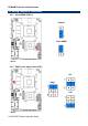
ECM-QM77 Quick Installation Guide 2.4 Audio / USB Daughter Board User’s Guide 2.4.1 Jumper and Connector Layout 2.4.2 Jumper and Connector List Connectors Label Function AUSB2 USB connector 2.0 AUSB3 USB connector 3.0 MIC1 Mic in connector Phone Jack LINEOUT1 Line out connector Phone Jack LINEIN1 Line in connector Phone Jack AJAUDIO1 Audio connector 6 x 2 header, pitch 2.00mm AJUSB2 2.00mm USB connector 5 x 2 header, pitch 2.00mm AJUSB3 2.
ECM-QM77 Quick Installation Guide 2.4.3 Setting Jumper and Connector Audio Connector (AJAUDIO1) Signal PIN PIN 2.00mm USB Connector (AJUSB2) Signal Signal PIN PIN Signal AFRONT1-L-OUT 1 2 AFRONT1-R-OUT USB2VCC 1 2 USB2VCC GND 3 4 GND AUSB_PN2 3 4 AUSB_PN1 ALINE1-L-IN 5 6 ALINE1-R-IN AUSB_PP2 5 6 AUSB_PP1 AMIC1-L-IN 7 8 AMIC1-R-IN GND 7 8 GND ALINE1-JD 9 10 AFRONT1-JD GND 9 10 GND GND 11 12 AMIC1-JD 2.
ECM-QM77 Quick Installation Guide 2.5 Installing the CPU 2.5.1 Locate the CPU socket on the board. Before installing the CPU, make sure that the socket box is facing towards you and the load lever is on your left.
ECM-QM77 Quick Installation Guide 2.5.2 Separate CPU cooler and its base first by screw drawer 1.
ECM-QM77 Quick Installation Guide 2. turn the CPU lock clockwise to lock CPU The CPU fits in only one correct orientation.