ECM-VX900 A.2. 3.5” VIA VX900 Micro Module Quick Installation Guide 1st Ed – 23 April 2012 Part No.
ECM-VX900 Quick Installation Guide FCC Statement THIS DEVICE COMPLIES WITH PART 15 FCC RULES. OPERATION IS SUBJECT TO THE FOLLOWING TWO CONDITIONS: (1) THIS DEVICE MAY NOT CAUSE HARMFUL INTERFERENCE. (2) THIS DEVICE MUST ACCEPT ANY INTERFERENCE RECEIVED INCLUDING INTERFERENCE THAT MAY CAUSE UNDESIRED OPERATION. THIS EQUIPMENT HAS BEEN TESTED AND FOUND TO COMPLY WITH THE LIMITS FOR A CLASS "A" DIGITAL DEVICE, PURSUANT TO PART 15 OF THE FCC RULES.
ECM-VX900 Quick Installation Guide first. To receive the latest version of the user’s manual; please visit our Web site at: http://www.avalue.com.tw/ If you still cannot find the answer, gather all the information or questions that apply to your problem, and with the product close at hand, call your dealer. Our dealers are well trained and ready to give you the support you need to get the most from your Avalue’s products.
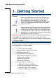
ECM-VX900 Quick Installation Guide 1. Getting Started 1.1 Safety Precautions Warning! Always completely disconnect the power cord from your chassis whenever you work with the hardware. Do not make connections while the power is on. Sensitive electronic components can be damaged by sudden power surges. Only experienced electronics personnel should open the PC chassis. Caution! Always ground yourself to remove any static charge before touching the CPU card.
ECM-VX900 Quick Installation Guide 2.
ECM-VX900 Quick Installation Guide 2.
ECM-VX900 Quick Installation Guide ECM-VX900 Quick Installation Guide 7
ECM-VX900 Quick Installation Guide 2.2 Jumper and Connector List You can configure your board to match the needs of your application by setting jumpers. A jumper is the simplest kind of electric switch. It consists of two metal pins and a small metal clip (often protected by a plastic cover) that slides over the pins to connect them. To “close” a jumper you connect the pins with the clip. To “open” a jumper you remove the clip. Sometimes a jumper will have three pins, labeled 1, 2, and 3.
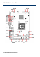
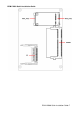
ECM-VX900 Quick Installation Guide Connectors Label Function Note BBAT1 Battery connector 2 x 1 wafer, pitch 1.25 mm COM1 Serial port 1 connector D-sub 9-pin, male CF1 CF card connector CF type II 50 pin CPU_FAN1 CPU fan connector 3 x 1 wafer, pitch 2.54 mm DIMM1 204-pin DDR3 SODIMM socket HDMI1 HDMI connector J422/485 Serial port 2 in RS-422/485 mode 3 x 2 header, pitch 2.0 mm JAUDIO1 Audio connector 6 x 2 header, pitch 2.0 mm JBKL1 +12V power connector 2 x 1 wafer, pitch 2.
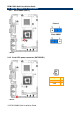
ECM-VX900 Quick Installation Guide 2.3 Setting Jumpers & Connectors 2.3.1 Clear CMOS (JBAT1) Protect* Clear CMOS * Default 2.3.
ECM-VX900 Quick Installation Guide 2.3.
ECM-VX900 Quick Installation Guide 2.3.4 Serial port 1 (COM1) signal selector (JRI1) +5V Ring* +12V * Default 2.3.
ECM-VX900 Quick Installation Guide 2.3.6 5VSB connector in ATX (PWR_SB1) Signal PIN ATX5VSB 3 GND 2 PSON 1 2.3.
ECM-VX900 Quick Installation Guide 2.3.8 Battery connector (BBAT1) Signal PIN +V3.3A 1 GND 2 2.3.
ECM-VX900 Quick Installation Guide 2.3.10 Serial port 2 in RS-422/485 mode (J422/485) Signal PIN PIN Signal 485RX- 2 1 485TX- 485RX+ 4 3 485TX+ GND 6 5 +5V 2.3.
ECM-VX900 Quick Installation Guide 2.3.12 +12V power connector (JBKL1) Signal PIN GND 2 +12V 1 2.3.
ECM-VX900 Quick Installation Guide 2.3.13 LCD Inverter Connector (JBKL2) Signal PIN +V5S 5 L_BKLT_CTRL_R 4 LVDS_BKLT_EN 3 GND 2 +V12S 1 Note: For inverters with adjustable Backlight function, it is possible to control the LCD brightness through the VR signal controlled by JVR1. Please see the JVR1 section for detailed circuitry information. 2.3.13.1 Signal Description – LCD Inverter Connector (JBKL2) Signal Signal Description L_BKLT_CTRL_R Vadj = 0.75V ~ 4.25V (Recommended: 4.
ECM-VX900 Quick Installation Guide 2.3.14 Serial port 2 connector (JCOM2) P Signal PIN DCD#_2 1 2 RxD_2 TxD_2 3 4 DTR#_2 GND 5 6 DSR#_2 RTS#_2 7 8 CTS#_2 RI#_2 9 10 NC N Signal 2.3.15 Low Pin Count connector (JLPC1) Signal 18 ECM-VX900 Quick Installation Guide PIN PIN Signal AD0 1 2 +V3.
ECM-VX900 Quick Installation Guide 2.3.
ECM-VX900 Quick Installation Guide 2.3.
ECM-VX900 Quick Installation Guide 2.3.18 PS2 KB/MS connector (JKB/MS1) Signal PIN PIN Signal KB_DT 1 2 KB_CK GND 3 4 PS2PWR MS_DT 5 6 MS_CK NC 7 Signal PIN PIN Signal +V3.3A 1 2 GND SS0 3 4 CLK DI 5 6 DO 2.3.
ECM-VX900 Quick Installation Guide 2.3.20 USB connector 0 & 1/ 2 & 3/ 4&5 (JUSB1_1/ JUSB2_1/ JUSB4_1) Signal PIN PIN Signal JUSB1_1 JUSB2_1 JUSB4_1 +5V 1 2 GND N1/ N2/N4 3 4 GND P1/ P2/P4 5 6 P0/ P3/P5 GND 7 8 N0/ N3/N5 GND 9 10 +5V 2.3.21 LCD backlight brightness adjustment (JVR1) Signal PIN +5V 1 L_BKLT_CTRL_R 2 GND 3 Variation Resistor (Recommended: 4.
ECM-VX900 Quick Installation Guide 2.4 Audio / USB Daughter Board (AUX-032) User’s Guide 2.4.1 Jumper and Connector Layout 2.4.2 Jumper and Connector List Connectors Label Function Note CN1, CN2 USB connector CN4 Line out connector Phone Jack CN5 Line in connector Phone Jack CN6 Mic in connector Phone Jack JAUDIO Audio connector 6 x 2 header, pitch 2.0mm JP1 2.54mm USB connector 5 x 2 header, pitch 2.54mm JP2 2.54mm USB connector 5 x 2 header, pitch 2.54mm JP4 2.
ECM-VX900 Quick Installation Guide 2.4.3 Setting Jumper and Connector Audio Connector (JAUDIO) Signal PIN PIN 2.54mm USB Connector (JP1) Signal Signal PIN PIN Signal OUTR 1 2 OUTL +5V 1 2 GND GND 3 4 GND D1- 3 4 GND INR1 5 6 INL1 D1+ 5 6 D2+ MICIN1 7 8 AREF GND 7 8 D2- FRONT-JD1 9 10 LINE1-JD1 GND 9 10 +5V MIC1-JD1 11 12 GND 2.54mm USB Connector (JP2) Signal PIN PIN Note: Wrong USB cable configuration with your USB devices might damage USB devices.